Surface Finish Symbols
Understanding surface finish symbols is vital in ensuring the success of any component outlined within an engineering drawing.

What Are Surface Finish Symbols?
Surface finish refers to a surface’s texture. A vital component in ensuring the successful creation of manufactured parts, surface finishes are outlined within engineering drawings to ensure that parts fit together tightly. For example, for a seal to be airtight, parts manufactured must have compatible surface finishes to prevent the occurrence of any friction or damage between the multiple surfaces.
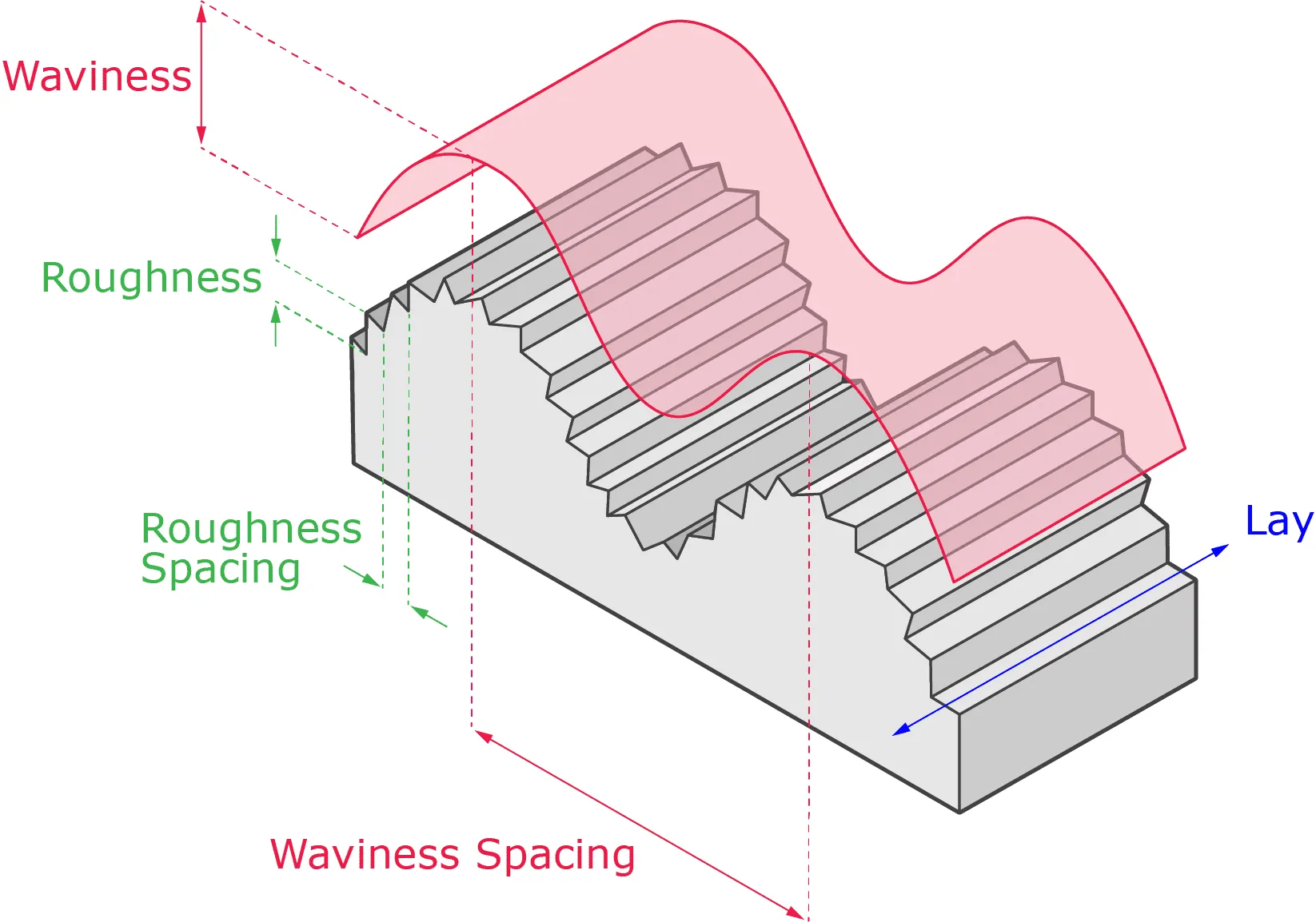
Surface finishing is also sub-categorised into three separate categories - waviness, lay, and roughness:
{{cta-banner}}
Waviness
The title is given to imperfections within the surface of a component, often caused by warping due to excessive heating and cooling, and machining defects such as those caused by chatter. Waviness is measured over an evaluation length, with waviness spacing a calculation of the peak-to-peak spacing of waves, with the average height meanwhile defined by average waviness.
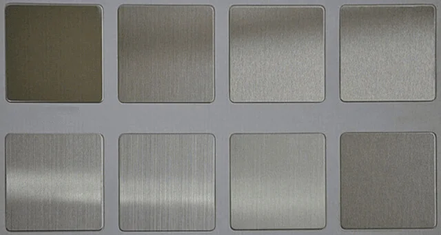
Lay
Produced by the manufacturing process undertaken to manufacture the component in question, lat is the dominant pattern of a part’s surface. It can be either parallel, perpendicular, circular, isotropic, multi-directional, or cross-hatched.
Surface roughness
Minor irregularities in the geometry of a component’s surface. Many engineer’s who reference surface finish will be referring exclusively to surface roughness, as this is the category most commonly measured. We go into more depth on what surface roughness means in our Surface Roughness Explained resource.
See below the diagram demonstrating the relationships between waviness, lay, and surface roughness:
To denote different surface finishes within different components, a list of surface finish symbols is required to reference contrasting finishes in a universally understood way. See below for a full list of all surface finish symbols, their meaning, and how they should be applied:
Basic surface texture symbol
Any method may be employed to produce the desired surface unless the circle or bar are specified, as illustrated within the symbols below.

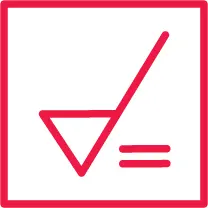
Material removal by machining is required symbol
This symbol indicates that material removal by machining is necessary for the desired surface finish to be achieved. A horizontal black bar is added to the basic surface texture symbol to indicate this.

Material removal prohibited symbol
Used to indicate that processes such as injection moulding, cold finishing, die casting, casting, forging, hot finishing or powder metallurgy must be used to acquire your desired surface finish. A black circle is added to the basic surface texture symbol to denote this.

Surface texture symbol
Applicable when a surface is produced via any possible method, excluding when a bar or circle is specified or a method is specified above the horizontal line.

Parallel to plane of projection symbol
An edged tool is used during machining to create creases parallel with the surface in the diagram in which the symbol is written.
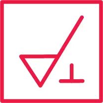
Perpendicular to plane of projection symbol
The creases made by the edged tool during machining are parallel to the surface captured in the diagram in which the symbol is written.
Crossed in two oblique directions to plane of projection symbol
An edged tool is used during machining to create creases at an angle to the plane of projection, crossing one another on the surface on which the symbol is written.

Multi-directional symbol
The edged tool employed during machining creates creases that cross multiple times or have no set direction.

Approx circular symbol
An edged tool is used during machining to create creases in the form of concentric circles in relation to the centre of the surface upon which the symbol is denoted.
Approx radial symbol
An edged tool is used during machining to create creases forming mostly a radial pattern in relation to the centre of the surface on which the symbol is written.

To access our full range of engineering resources, visit our technical toolbox.
Leave it to our manufacturing specialists
Get a 24 hour, engineer made quote and design review to start your manufacturing project off on the right foot

Get your production-ready quote in 24 hours
All projects are reviewed by real engineers to ensure accuracy, catch mistakes and unlock DFM improvements


Our services
From 3D printing to CNC machining, we’re experts in manufacturing bespoke precision parts on tight time-frames

Other services
It’s rare you only need CNC machining services. We offer 3D printing, moulding, casting, extrusion, fabrication, assembly, welding & more.
Get your production-ready quote in 24 hours
All projects are reviewed by real engineers to ensure accuracy, catch mistakes and unlock DFM improvements
Working with Get It Made for all our prototyping was an absolute pleasure. Next to immediate response, fast lead times, often arriving before the stated date. Their attention to detail and customer service were second to none. and all at the most competitive price point that could't be beaten in the U.K.

Get It Made are at top of their game when it comes to reliability and quality. We trust Get It Made to deliver parts on time and within tolerance. We can't speak highly enough of their customer service. Get It made are quick to reply to enquiries and keep you well informed throughout the whole process.

Get It Made were able to deliver an accurate and quick service delivering a set of high fidelity prototypes expertly finished, ready for user testing. They offered a range of fabrication options and materials to choose from, tailoring the service to our specific budget, timeframe and material requirements. Can't recommend enough.

Get It Made have over the years been able to take on from simplest to the most complicated of jobs with ease, providing expert advice, good prices and reliable lead times. No job has been too big or too small, either in size or volume. We would strongly recommend Get It Made; you won't be disappointed!

We initially started working with Get It Made, as we needed a high quality product developed within a very short lead time. The entire process went very smoothly and we received the products ahead of schedule. We were pleased with the final results and we found working with Luke very easy, as he offered good technical advice.

When we were looking to have parts manufactured, we had tight deadlines with an even tighter budget. Get It Made understood our constraints and worked with us closely to get our parts to a higher standard than we expected. I can not recommend Get It Made enough. They are professional, communicative, and the parts are fantastic.

The Get It Made team are very responsive and knowledgeable, fully owning a project throughout, providing superb communication. Transparent pricing structure and rapid quotation turnaround is by far the quickest I've experienced, reducing time to manufacture. Get It Made are a pleasure to work with.

Bespoke quote in 24 hours
Get It Made is proud to provide a human service. Get a quote and free design review by an experienced engineer to see how we make manufacturing simple.