Thread Terminology
This resource will touch upon all the key areas you will need to correctly define your threaded holes on your parts. It will teach you the standardised format for defining threaded holes and some best practices along the way.

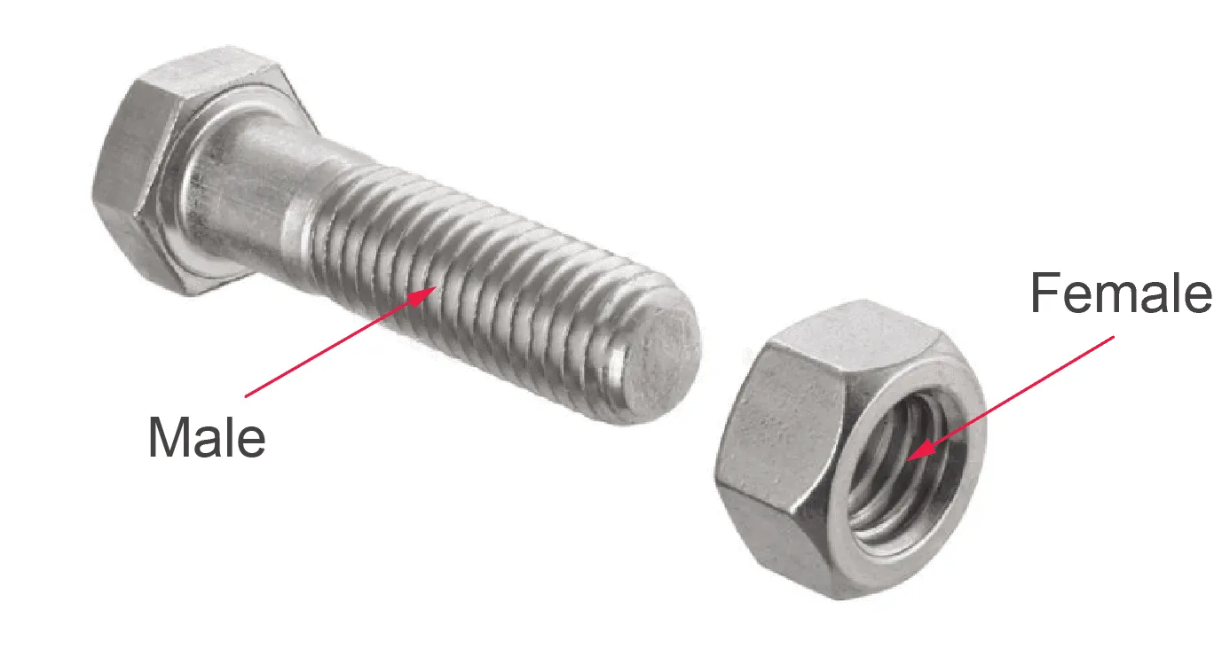
Threads are used to attach two separate parts together, and every thread has a matched pair of external threads (male) and internal threads (female). The most common form of the fastener being a nut and bolt, the nut having a thread cut on the inside of a cylindrical body (female) and the bolt having a thread cut on the outside of a cylindrical body (male).
Thread Terminology
The following diagram illustrates the key dimensions when defining a thread:
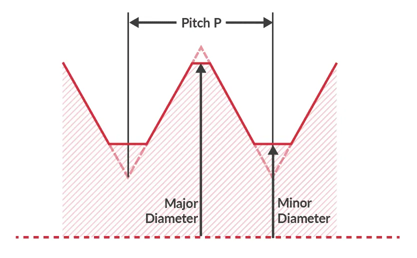
Major Diameter - The Major Diameter is the largest diameter on the thread and is measured from the thread crest to crest (peak of the thread).
Minor Diameter - Minor Diameter is the smallest diameter on the thread and is measured from the thread root to root (Bottom of the thread).
Pitch - This is the distance (mm) from one thread to the next, this can be measured from tip to tip or groove to groove. Pitch can also be defined as TPI, which stands for threads per inch.
Thread Angle - The angle between the thread faces.
Right-Hand Thread - The thread will assemble when rotated clockwise. "righty tighty lefty loosely"
Left-Hand Thread - The thread will assemble when rotated counter-clockwise.
{{cta-banner}}
Internal Thread Symbols
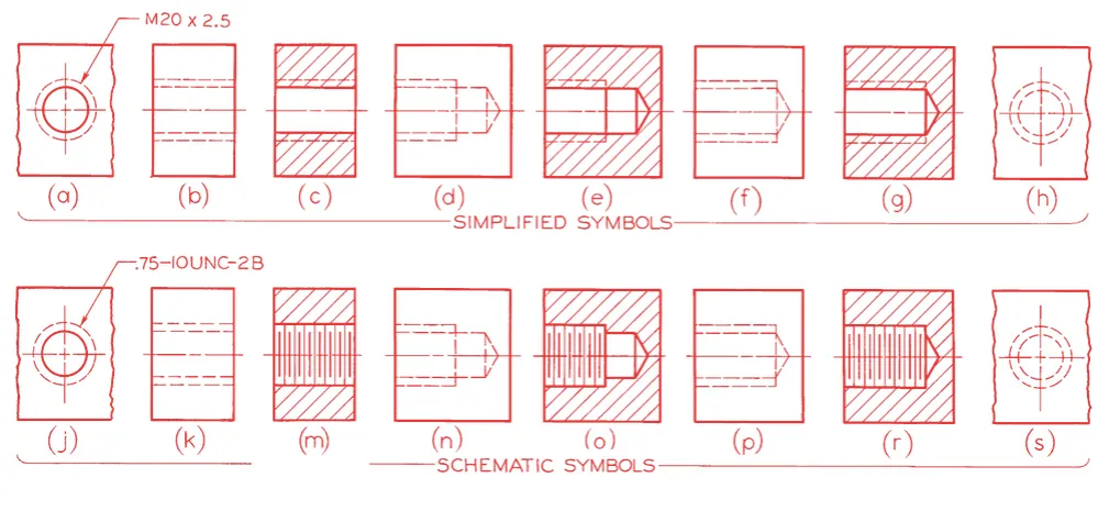
The image below shows the symbols you can expect to see on an engineering drawing when a threaded hole is present.
Metric and Inch Threads Explained
Metric Threads
A metric thread is defined with the thread series designation 'M' followed by the nominal diameter and pitch, in millimetres. If the pitch is not specified, it is considered a coarse thread, as shown below our coarse metric thread chart. This is an ISO standard to simply the designation of coarse threads, so you don't have to memorise the thread pitches. All threads are assumed to be right-handed unless specified.
Consider a M8 x 1.0 thread:
M = Metric thread designation
8 = Nominal diameter (mm)
1.0 = Pitch (mm)
Inch Threads
An inch thread is defined with the nominal major diameter first and then the number of threads per inch second. All threads are assumed to be right-handed unless specified. This designation is more commonly used in North America.
Consider a 3/8 - 16 thread:
3/8 = Nominal major diameter (inch)
16 = Number of threads per inch
A 3/8 - 16 thread would be considered a coarse thread, a 3/8 - 24 thread has the same nominal diameter; however, it has more threads per inch, making it a fine thread.
Class Fit
When the male and female threads are mated, the two parts assemble together with a degree of tightness dictated by the fit of the two threads. Three sets of thread classes have been created to define the tightness between the threads. There is a unified thread form, and the classes of fit are:
Class 1 - Loose fit. Threads will assemble quickly by hand. This is useful when frequent assembly and disassembly is required. It is recommended to use a locking device (lock washer, locking nuts, etc.) when using this class of fit. A Class 1 fit is found on most nuts and bolts.
Class 2 - Standard it. Threads will party assemble by hand but will require the use of tools. This type of fit is for assemblies that will require disassembling every so often but not permanently. Class 2 is the most common fit used.
Class 3 - Tight fit. This fit can often be started by hand but will always require tools to fully assemble. This fit is used for permanent assemblies that do not require disassembling. Class 3 is commonly used for set screws.
Callouts
Callouts are included on an engineering drawing to specify specific information for a feature to the manufacturer. The four most commonly used callouts are highlighted below:
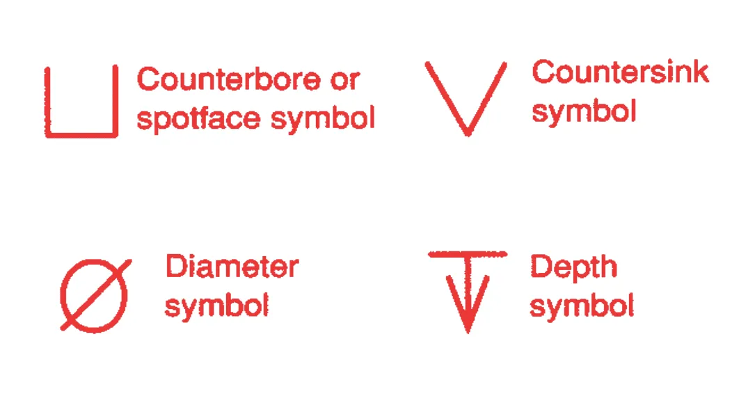
Counterbore - Secondary machining operation used to create a larger cylindrical hole for recessing a fastener head.
Countersink - Secondary machining operation used to create a conical shape for recessing a fastener head.
Diameter - The diameter is defined if the pilot hole drilled prior to the threading is unique. The diameter of the pilot hole sets the minor diameter for internal threads.
Depth - The depth of a thread is defined as either thru or blind. A thru thread is all the way through the workpiece, so depth does not need to be determined. It is a common mistake to put "THRU" as a callout for a thread. If no depth is specified, by default, the thread is a thru hole. A blind thread is machined to a specific depth, so a depth callout is needed.
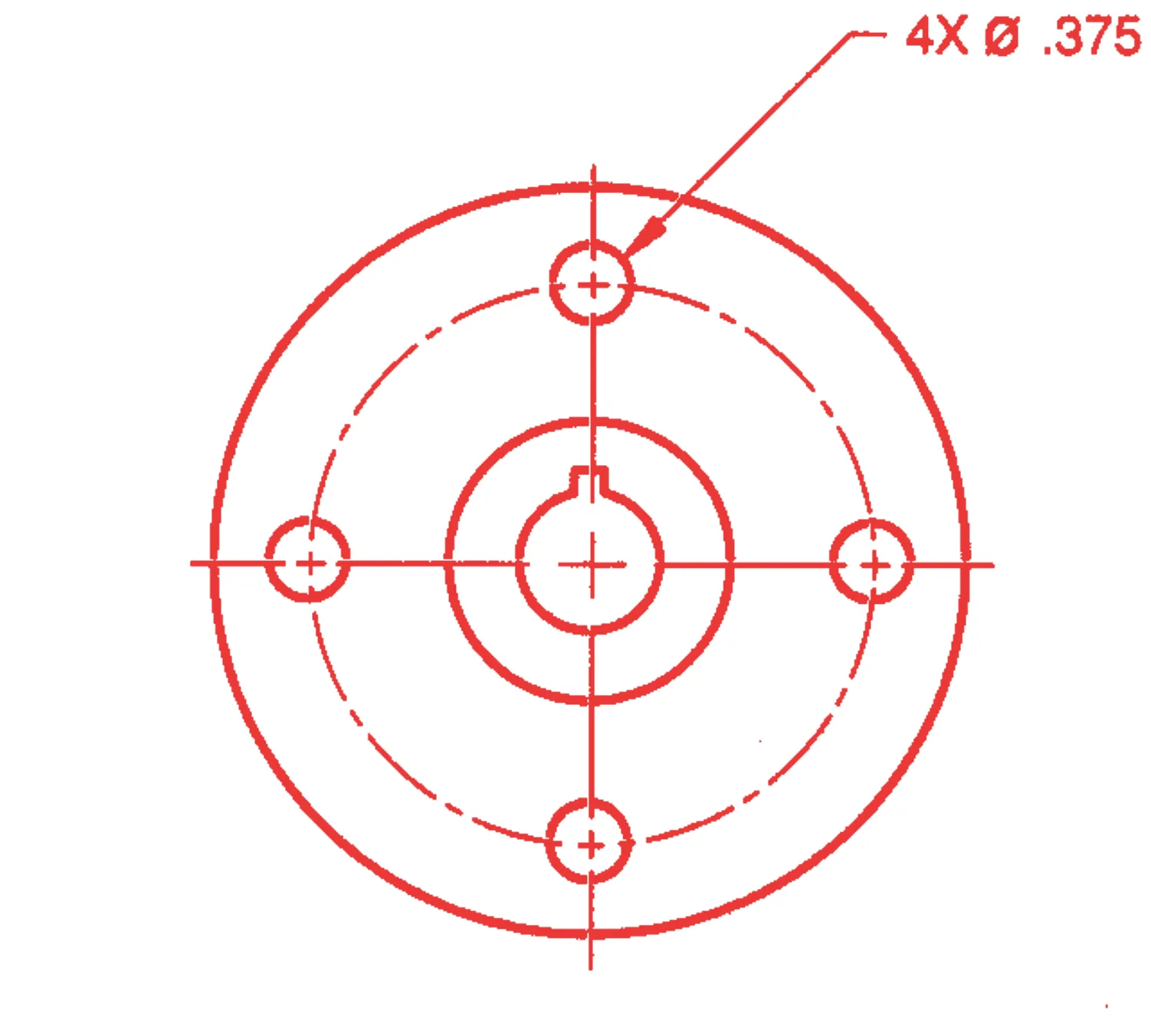
Multiple Occurrences - When the same threading operation is required on multiple of the same hole, it is not necessary to add callouts for every hole. It is best to write the callout on one hole and include the number of identical threaded holes in the note. An example of how correctly display this callout is shown below.
Types of Fasteners
There is a wide range of mechanical fasteners available on the market, in this section, we will show you the six most common fasteners you can expect to find along with the recognised standard abbreviation for each type.
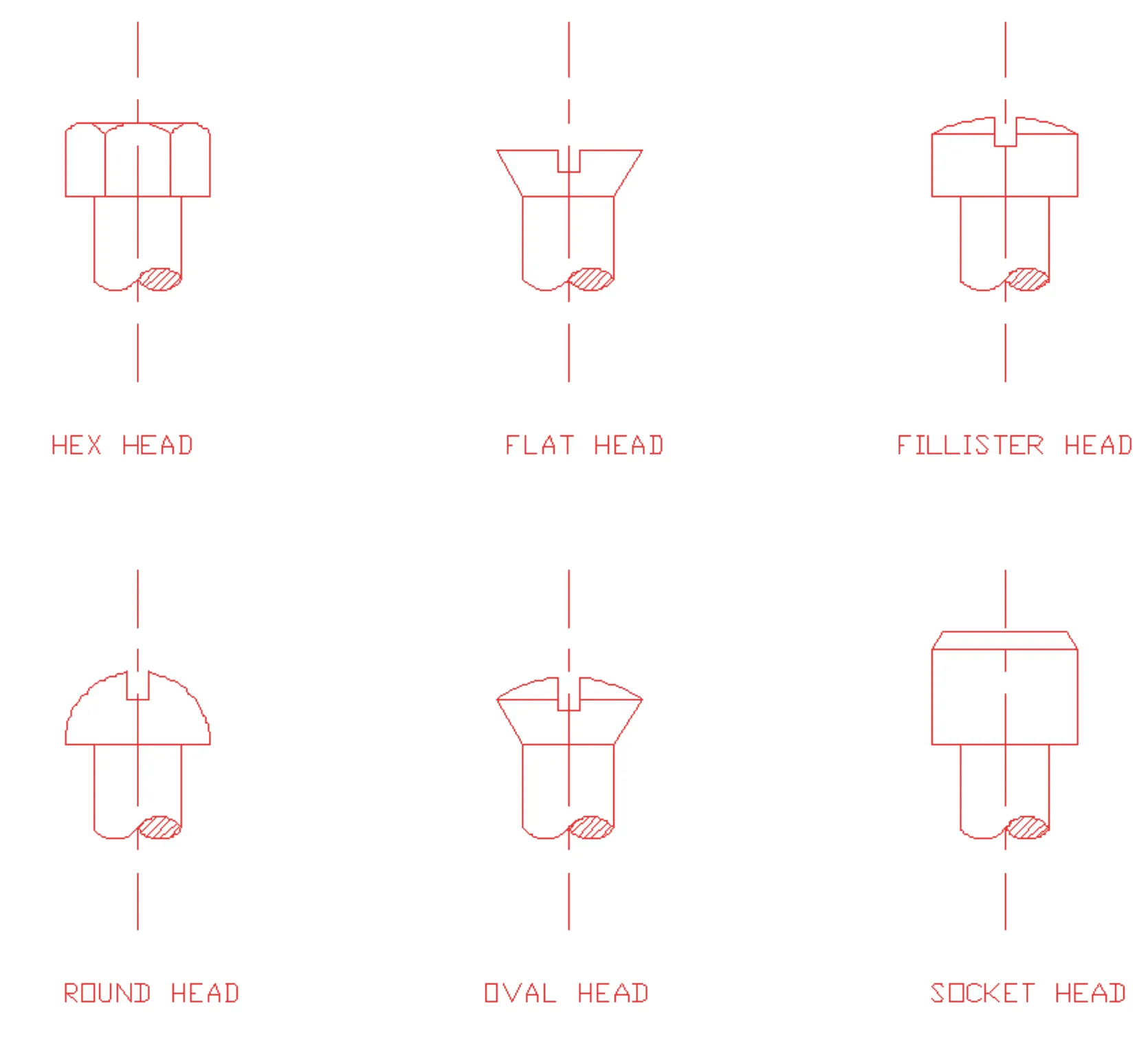
- Hexagonal Head (HEX HD)
- Flat Head (FLAT HD)
- Fillister Head (FIL HD)
- Round Head (RND HD)
- Oval Head (OVAL HD)
- Socket Head (SOC HD)
View our complete chart of metric threads.
To find more helpful engineering information, head over to our guides page to learn how to design your parts for production perfectly! Or, if your parts are all ready for production, get a free 24-hour quote from us now.
Leave it to our manufacturing specialists
Get a 24 hour, engineer made quote and design review to start your manufacturing project off on the right foot
Get your production-ready quote in 24 hours
All projects are reviewed by real engineers to ensure accuracy, catch mistakes and unlock DFM improvements
Our services
From 3D printing to CNC machining, we’re experts in manufacturing bespoke precision parts on tight time-frames
Other services
It’s rare you only need CNC machining services. We offer 3D printing, moulding, casting, extrusion, fabrication, assembly, welding & more.
Get your production-ready quote in 24 hours
All projects are reviewed by real engineers to ensure accuracy, catch mistakes and unlock DFM improvements
Bespoke quote in 24 hours
Get It Made is proud to provide a human service. Get a quote and free design review by an experienced engineer to see how we make manufacturing simple.


