

Geometric Dimensioning and Tolerancing
This resource will teach you everything you need to know about Dimensioning and Tolerancing for your parts.
What is Dimensioning?
Before a part can be manufactured, specific information on the size and shape must be communicated through an engineering drawing or Model Based Definitions (MBD). Within this engineering drawing, the dimensions of key features are defined. A correctly dimensioned part should communicate the designer's intentions to the manufacturer and quality inspector. In the UK, dimensions included within engineering drawings are expressed in millimetres and should follow British standards. Information on said standards can be found here.
What is Tolerancing?
Tolerancing is the most common callout on an engineering drawing and defines the acceptable range a feature can vary from its specified dimension. To correctly tolerance a component, the designer must have an in-depth knowledge of how the part will function. For example, if manufacturing a drill head, a tolerance would need to be defined to ensure that the tool would still be usable regardless of the variation from the desired value. If the diameter of the tool was 10 mm and had a tolerance of ±0.02 mm, the maximum diameter the tool could be is 10.02 mm and the minimum 9.98 mm.
{{cta-banner}}
What is Geometric Dimensioning and Tolerancing?
Geometric dimensioning and tolerancing, sometimes known as GD&T, was introduced during the 1950s as a more accurate and cost-effective method of dimensioning and tolerancing mechanical parts. This system comes from The American Society of Mechanical Engineers, and while it is colloquially referred to as GD&T, its official title is ‘ASME Y14.5 Dimensioning and Tolerancing’. In addition to American standards, the International Organisation for Standardisation (ISO) also exists, an international standard for dimensioning and tolerancing. Dictated via symbols rather than individual notes, engineering drawings can be understood between countries without any translations.
Using computer-aided design (CAD) technology, GD&T enables designers and engineers to fully define how a part should be manufactured to function correctly. This is achieved via the use of a range of symbols that are outlined in the table below.
Geometric Dimensioning and Tolerancing Symbols Chart
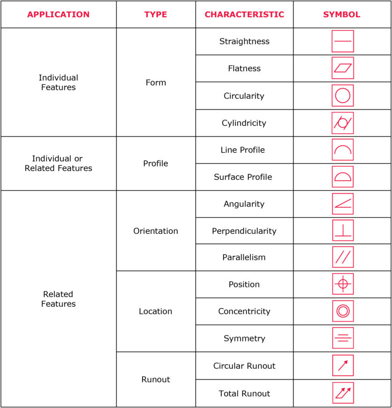
Meaning of symbols (in order of above table)
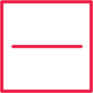
Straightness - A 2D tolerance that can be applied to surfaces within 2D and 3D components. Most commonly, this is used to dictate the form of a line along the surface of a manufactured part; this is referred to as surface straightness. Alternatively, it can also be employed as a tool in which the curve of a line along an axis of a component can be controlled.
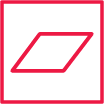
Flatness - A reference of how flat a surface is, regardless of feature size (RFS), and without requiring a datum. Always less than the dimensional tolerance, a flatness tolerance is referenced between two planes parallel to the surface being measured and is measured via a height gauge moved across the part’s surface, parallel to said reference planes.

Circularity - A two-dimensional tolerance employed to measure how close a tool or object should be to a perfect (true) circle. Like flatness, this unit of measurement does not require a datum and is measured by rotating a part around its central axis, as a height gauge tool calculates surface variation. The tolerance zone of this measurement is measured via two concentric circles. The measurements must be within these two minor and major circles to be within tolerances.

Cylindricity - The three-dimensional equivalent of circularity, this unit of measurement is used to determine how close a tool or object measures to a true cylinder. To measure this, concentric cylinders are placed internally and externally to the original piece, between which the entire surface area of the tool must reside, establishing a tolerance zone. To ensure that the manufactured part being measured is suitable, its measurements must fall between the two cylinders, the desired tolerance zone.
Line profile - A two-dimensional tolerance zone placed around any potential line within a manufactured part. Traditionally the profile employed to establish the tolerance profile of curved lines, this tolerance zone is achieved via a cross-section along the line, with parallel lines abiding by the true surface profile placed on either side of the said cross-section. To achieve its desired line profile, the piece's surface must fall within this tolerance zone.
Surface profile - A three-dimensional tolerance zone used for a curved surface. Its tolerance zone is achieved via two parallel lines/curves mimicking the shape and profile across the entirety of the surface length. Due to the potentially complex nature of the shape in question due to its curved surface, a coordinate measuring machine is used to calculate the piece's exact profile. Once these measurements are taken, they can then be compared to the desired specifications of the original engineer drawing and whether they fall within the tolerance zone.
Angularity - Denotes the orientation of one feature of a manufacturing piece to another at a referenced angle. With the help of a datum, the tolerance zone indirectly dictates the angle of the piece since it determines the final positions in which the surface can be placed. The process of measuring angularity is carried out by positioning a part to the pre-determined reference angle. A height gauge then measures the now flat horizontal surface, measuring whether its variation falls within the necessary variation zone.
Perpendicularity - This can be separated into two distinct categories - surface perpendicularity and axis perpendicularity. The former is a tolerance that controls Perpendicularity between two 90° surfaces, while the latter is a tolerance that controls how perpendicular a specific axis needs to be to a datum.
- Surface perpendicularity requires the referenced surface or line to be perpendicular or 90° from a datum surface. As well as being able to reference a two-dimensional line, it can also reference a surface perpendicular to the datum.
- Axis perpendicularity can be applied to both positive and negative features and specifies the cylindrical boundary where the axis of the referenced component must lie.

Surface Parallelism - A tolerance that controls parallelism between two surfaces or features. Two parallel lines, either side of the surface being measured, denote the tolerance zone. As a result of this denotation, surface parallelism can dictate the final angle of a manufactured part, much like angularity.
Position - One of the most widely used symbols in the entirety of machining, position (commonly referred to as ‘true position), references the total permissible variation that a feature can have from its “true” position. Position is a concept transferrable between two-dimensional and three-dimensional components. By using datum planes and axes as references, the position can shape tolerance zones for all manufactured components.

Concentricity - Concentricity is a 3-Dimensional cylindrical tolerance zone that is defined by a datum axis where all the derived median points of a referenced cylindrical feature must fall within. All median points along the entire part must be in this tolerance zone. It is regarded as a complex symbol to measure due to difficulty identifying median points within the feature. This process requires the establishment of a datum axis and a number of cross-sections necessary to locate diametrically-opposed surface points, which can subsequently be compared to the tolerance zone established via the datum axis. This comparison enables us to identify whether or not the surface points fall within the necessary parameters of the tolerance zone required for assembly.

Symmetry - Within GD&T, symmetry acts as a three-dimensional tolerance, which ensures that features on a component are uniform across a datum plane. Via the use of a datum, a true central plane is established, and in order for symmetry to be achieved within the desired tolerance, the median distance between points on both surface features must fall within that central plane.

Circular runout - The extent to which a feature(s) may vary in accordance with another datum when a part is rotated 360 degrees around the datum axis.

Total runout - The extent to which an entire surface may vary in accordance to a datum when a part is rotated 360 degrees around the datum axis.

Datum - A theoretical axis, plane, or point that all geometric dimensioning and tolerancing is referenced to. Due to its importance in tying a piece together, a datum must be carefully controlled during measurement.

Maximum Material Condition - Details the condition of parts where the maximum volume of materials exists within its dimensional tolerance.
The cost of applying tight tolerances
One common error often seen in the design of prospective components is the process of over-tolerancing. Whilst often desirable, tight tolerances are not always required for the success of every surface manufactured. Therefore, it is recommended to apply tight tolerances to design critical features and apply a relaxed general tolerance to the rest of your features. Criteria such as the desired function of the part, the process for which it is being manufactured, and the material it is made from are all crucial in determining the final tolerance required. The negatives of over tolerancing can be three-fold:
Cost of precision tools
To achieve a specific tight tolerance, precision machinery is often employed. Whilst this can achieve the desired specifications of the design, the machinery used to achieve this can be very expensive. If a tight tolerance is not required, this costly manufacturing method can be avoided.
Increased machining time
Additional processing steps will be required to reach the precise design specifications for a surface with tight tolerances. To supplement precision machining equipment, manual tasks such as grinding and polishing are undertaken, both of which are time-consuming and expensive. Furthermore, due to the increased difficulty required to achieve tight design toleranced surfaces, there is a greater rejection rate of manufactured parts.
Inspection
Critical tolerances often require a more precise inspection, such as measuring using a Coordinate-measuring machine (CMM). This increases both the cost and the overall manufacturing time for a project.
Useful Resources
Several useful resources are available for those still wanting to learn more regarding geometric dimensioning and tolerancing.
For further reading on master tolerances for machined parts, click here
For tips specifically on maintaining tight tolerances, click here
For those wishing to watch a video tutorial, see the video below:

Football fan ⚽️


Need custom metal and plastic parts?
Get 10% off your first order
No newsletter, no marketing, just a discount code for custom parts.

.webp)


