Plastic Injection Moulding Design Guide
Learn how to design your parts for Injection Moulding with our comprehensive how-to guide.

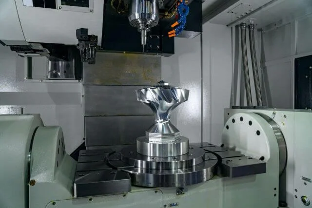
When choosing to design a product for plastic injection moulding, several considerations should be considered during the design stage to optimise the mould's ability to turn out a perfect part.
Get It Made are the leading provider of CNC Machining services UK wide. For more information about our range of CNC machining services or more about our injection moulding services, contact us today for a direct quote.
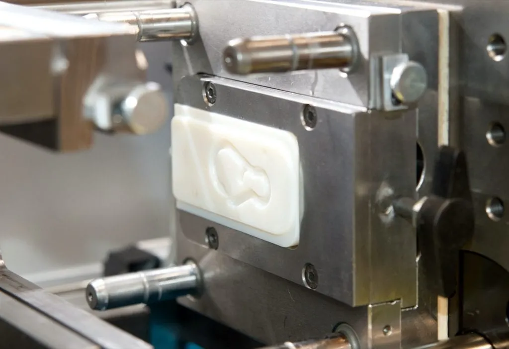
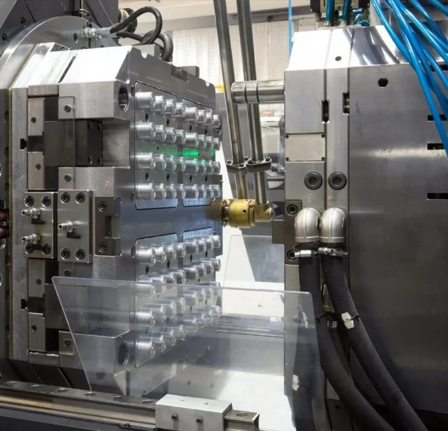
What is Plastic Injection Moulding?
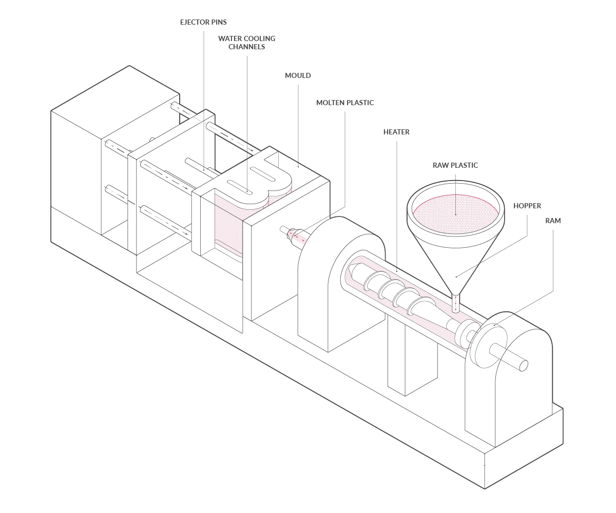
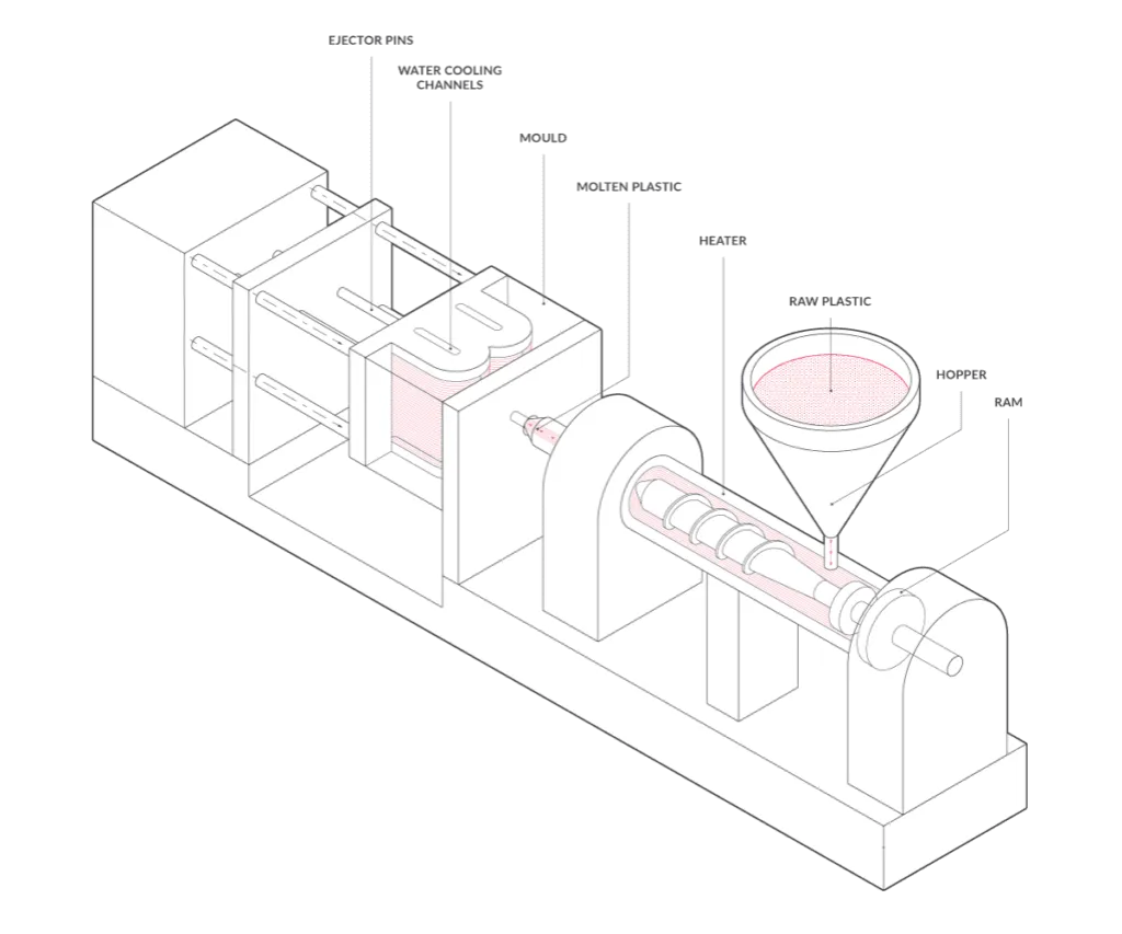
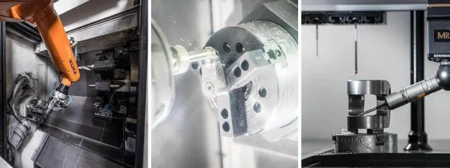
Injection Moulding is a manufacturing process used to produce plastic parts of large volume and capacity through the use of CAD (Computer-Aided Design). After the part's design is finished, a mould is created and machined with precision to form the part’s features. The injection moulding is accomplished when a thermoplastic or thermoset material is fed into a heated barrel, mixed and then forced into the metal mould cavity, where it then cools and hardens before removal.
There are various design components involved in the plastic injection moulding process. For more information about what injection moulding is, read our guide on the process of injection moulding.
Our Plastic Injection Moulding Design Guide provides tips, guidance and best practices for optimising your plastic injection moulding designs.
{{cta-banner}}
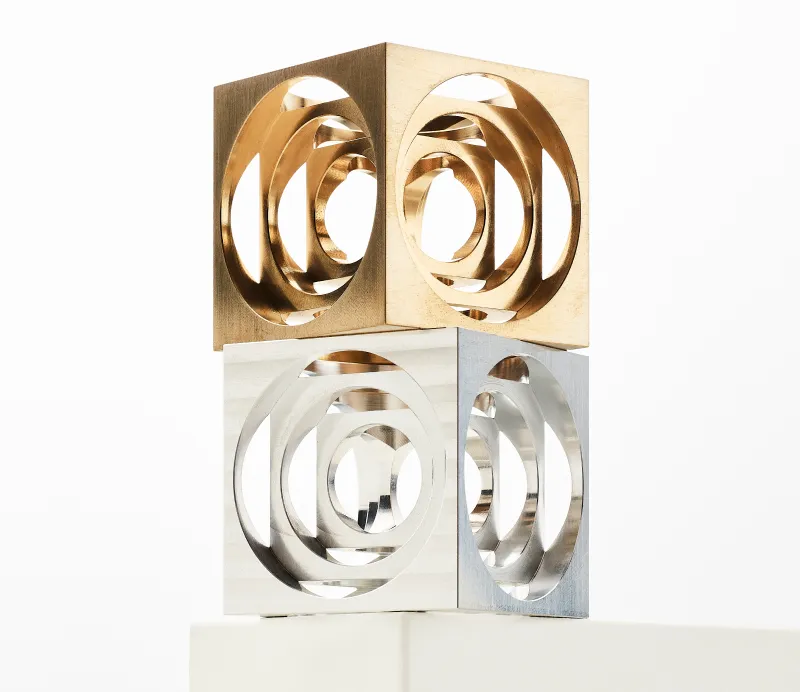
Types of plastic that can be used in plastic injection moulding
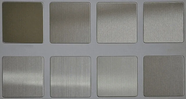
Here at Get It Made, we can injection mould the plastics pictured below in a wide variety of colours. Your chosen plastic will depend on various factors, including mechanical properties, aesthetics and cost.
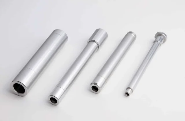
Products that can be made using plastic injection moulding
Generally speaking, the types of products that can be designed with plastic injection moulding are usually:
- Varied in size, from very small paper clips to large dustbins
- Lightweight
- Not subject to extreme forces
Plastic Moulding Design Guidelines
When designing parts for injection moulding, it is crucial to follow design guidelines and best practices to ensure consistent output from the injection moulding machine.
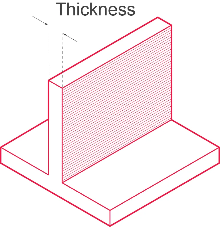
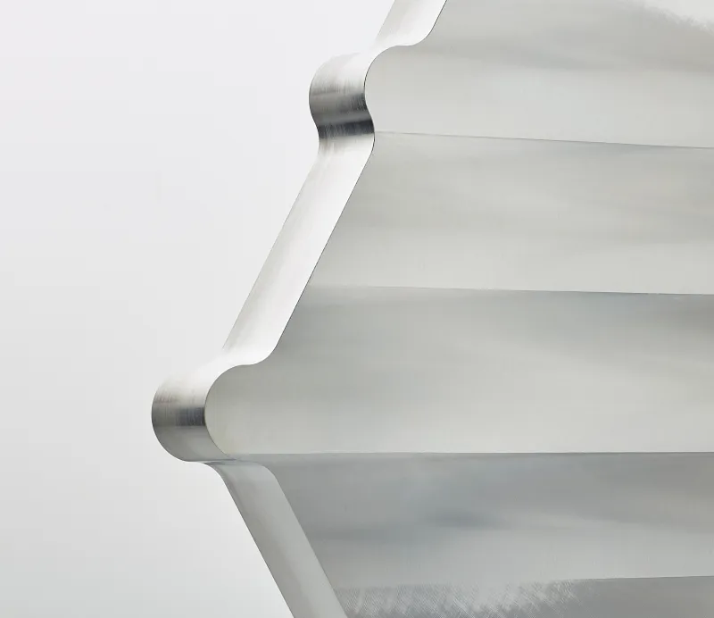
Wall Thickness
Like all other types of manufacturing, the wall thickness of the part is always a consideration.
The cost savings are at their highest when the walls have a minimum thickness. The thickness has to be in line with the function of the part and meet all other mould filling needs, but a thin wall also cools faster, which ensures cycle times are short and allows for more parts to be produced per hour.
However, it’s essential to consider the particular project, as this can ensure that the wall thickness provides adequate mechanical strength.
Thin parts also weigh less and use less material per part. The wall thickness of injection moulded parts ranges from 2mm to 4mm. Thin wall moulding can create walls as thin as 0.5mm.
Wall thickness will also depend on the material used, as material flow rate will influence the minimum wall thickness required.
- Recommended wall thickness of 1mm-4mm
- Other thicknesses are achievable dependent on material and application
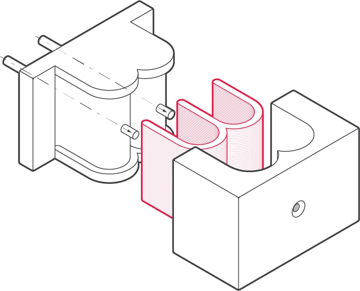
Uniform Walls
Parts with uniformly thick walls allow the mould cavity to fill easier since the molten material isn’t forced through different restrictions when it fills. In the injection moulding process, if the walls do not retain uniformity, then the thinnest section will cool first, and the thick section will cool and shrink, which creates stress near the boundary area.
Since the thin section will have already hardened, it leads to twisting or warping on the part, which can cause cracking.

What if you cannot have uniform walls?
When the design does not allow for a uniform thickness, it should be made as close as possible.
When the plastic is removed from the thicker area, it is typically done through coring, which keeps wall sections in uniformity and eliminates the problem.
If support structures are needed to reduce warping, gussets are often used.
Shrinkage
Shrinkage can be due to a lack of uniformity with the wall’s intersection.
This includes:
- Bosses
- Ribs
- Any protrusion on the nominal wall
Since the thicker wall will take more time to solidify, the cooling rate will differ from that of the nominal wall, resulting in a sunken area in the nominal wall.
This effect can be reduced if a rib thickness is kept between 50 and 60% of the walls they are attached to. If a boss is located in a corner, it will produce thicker walls, which can cause sinking unless the boss is isolated.
Warping
The dynamics between thicker and thinner sections and their related cooling times can result in warping. This is caused by the thick section shrinking as it cools with the material drawn towards the molten centre.
Other reasons why warping might occur include:
- Injection pressures
- Packing problems
- Cooling rates
- Moulding process conditions
- Uneven or too low mould temperatures
The manufacturer’s process guidelines for each plastic should always be considered.
Rib orientation and height
Isolate bosses from walls
If not correctly positioned, the positioning of bosses, ribs, or any protrusion on the nominal wall can cause non-uniform wall thickness issues. This can be reduced if the rib or boss thickness is kept between 50% and 60% of the walls they are attached to or isolated entirely. Alternatively, consider increasing the overall wall thickness if this is not possible.
Align ribs to part loading forces
Ribs can be orientated to provide strength aligned with bending loads by carefully considering the geometry.
Rib height should not be more than three times its thickness; multiple ribs can be used to give a greater degree of bending stiffness rather than using a tall rib.
Ribs increase the bending stiffness of a part without the added thickness. This occurs by increasing the moment of inertia, thus increasing the bending stiffness. This equation is Bending Stiffness = E (young’s Modulus) x I (moment of inertia).
The thickness of the rib should not be in excess of 60% of the nominal thickness, and the rib should have as generous an attachment to the corner radii as is possible.
Rib Intersections
The rib intersections are where the material is at its thickest, so either coring should be used to reduce any sizable shrinking from happening on the other side.
Rib height
Rib height should not be more than 3x its thickness; multiple ribs can be used to give a greater degree of bending stiffness rather than using a tall rib.
Effect of Rib or Load on Thickness
Ribs are added to provide additional bendable stiffness; by considering the geometry carefully, ribs can enhance stiffness by matching the rib orientation with the bending load.
Draft
Designers undertaking injection moulding need to remember to apply a draft or a taper to the part face to improve the mouldability of the part. An absence of any draft can prevent the parts from ejecting from the mould, which damages both the part and the mould itself and is costly and time-consuming.
It is suggested to give as much draft angle as is possible, generally at least 1 degree for every 25mm of cavity depth.
- Advised draft angle: 1 degree per 25mm cavity depth
- Minimum advised draft angle: 0.25 degrees
Part removal depends upon mould drafts that must be at an offset angle perpendicular to the mould’s parting plane. The best angle for any part will depend upon the part’s depth and the end-use function of the part.
Parts will release the easiest when as much draft as possible is allowed. A typical 1-2 degrees of draft and an added 1.5 degrees for every .25 of depth texture is best practice. The part line has to be placed in such a way that splits the draft. A side action mould is normally used when no draft is acceptable.
It is suggested to give as much draft angle as is possible. The following suggestions are standard rules applied in the industry:
- Give at least 0.5 degrees on all vertical faces.
- 1 to 2 degrees works very well in most situations.
- Three degrees should be considered the minimum for a shutoff - A shutoff is contact between two sliding metal surfaces in the mould.
- Three degrees is required for lightly textured surfaces.
- Five or more degrees is required for heavily textured surfaces.
Textures and Lettering
Lettering can be included on a mould surface where desired, and any surface defects can be hidden by texturing. As previously mentioned, extra draft would need to be added to allow the part to be easily removed with marring or dragging the part. In general, a draft for texturing will depend on the design of the part and the specific texture being used. 1.5 inch minimum per .001 inch is used with a minimum recommended draft of 1.5 inches. Heavily textured surfaces, such as leather, might need more. For example, a depth of .125 per .005 inch requires a minimum draft of 7.5 inches.
Sharp Corners
Internal stresses can be caused by sharp corners, leading to a part failure.
On corners, it is recommended to have an inside radius of 0.5 times the material thickness and keep the outside radius at 1.5 times the material thickness. A larger radius should be used if the part design allows for it.
- Inside radii > 0.5x wall thickness
- Outside radii > 1.5x wall thickness
The concentration of stress is significantly increased with sharp corners, leading to failure if high enough.
The overall radius of a sharp corner should be overseen due to the variance of stress concentration factors with a radius for any given thickness.
The corner radius divided by the wall thickness is commonly referred to as R/T. Stress concentrations are high for R/T values less than 0.5. R/T values greater than 0.5 will see stress concentrations lower. Inside radii are recommended to be within a minimum of one times that of the thickness.
Radii reduce stress by providing a streamlined flow path for the molten plastic, which makes the filling of the mould easier.
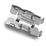
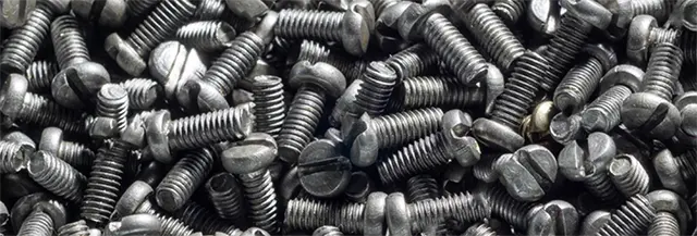
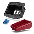
Inserts
Inserts are used to create a place for bolts or other fasteners. Their advantage is that they are stronger than the underlying plastic and usually made of brass, making for a robust part. Inserts allow for many cycles of assembly and disassembly and are installed within an injection moulded part using one of the following methods:
Press Inserts
Press inserts are applied to plastic parts after moulding. They can often be used whilst the plastic is still warm and malleable. Sometimes they can also be screwed into the part. Inserts are usually made from brass.
Ultrasonic Insertion
Inserts can be vibrated into place through the use of an ultrasonic transducer called a horn mounted in the ultrasonic device. Horns are typically designed for each application to create optimal performance. The ultrasonic energy is converted to thermal energy through the vibrations, melting the insert into the hold. This is quickly completed and allows for minimum time spent in the cycle as well as results in low residual stress.
Thermal Insertion
This uses a heated tool, like a soldering iron, to heat the insert until melting point and press it into place. The plastic cools, shrinking around the insert and acts to hold it in place. This method is advantageous because it is inexpensive and easy. The plastic should not be overheated; otherwise, the insert could have a loose fit, and the plastic could degrade.
Moulded In
Core pins are used in this method to mould inserts into place within the moulding cycle, giving a high retention level. The moulding cycle might be slowed down in this process due to the handloading of the inserts, but there will not be the need for secondary operations like the methods above. High volume production runs use an automatic tool for loading inserts, creating more cost and a higher degree of complexity.
Living Hinges
Thin, flexible plastic sections that join two parts together and act as a hinge is known as a “living hinge”. The living hinge allows a single moulded part to open and close. These hinges are used in high volume application containers such as lunch and toolboxes.
The material used in moulding a living hinge must be highly flexible such as polyethylene or polypropylene. If a living hinge is well designed, it can flex over a million times without failing.
Other types of Injection Moulding
Gas Assist Moulding
To hollow out a thick section of a part when coring cannot be employed, gas assist moulding can be used. It can be applied to nearly every type of thermoplastic, and most moulding machines can be adapted for this method.
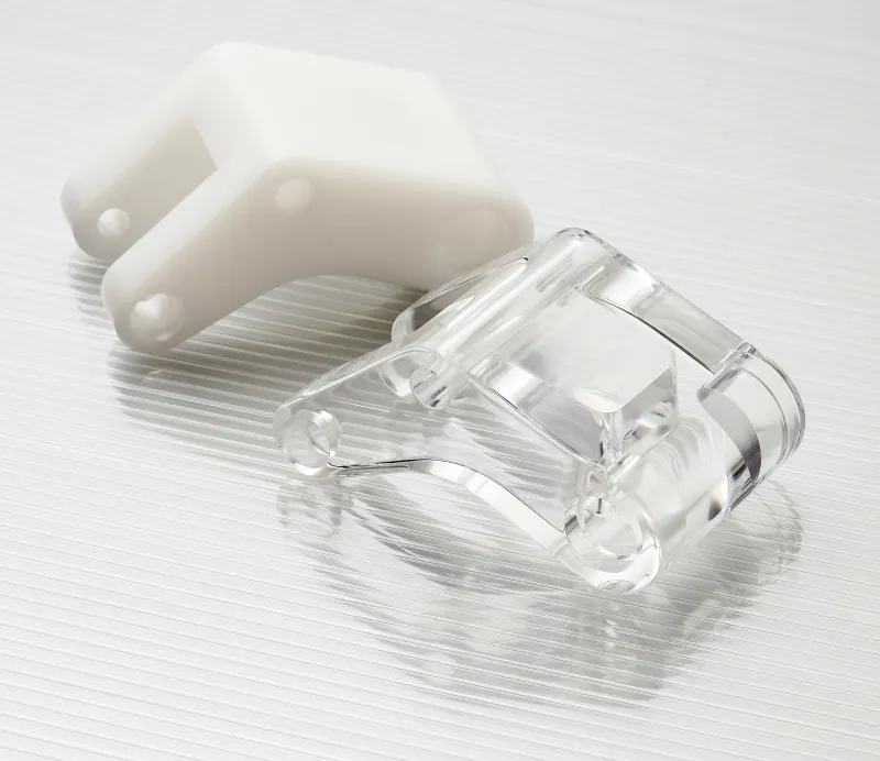
Overmoulding / Insert Moulding
This process is when a flexible material gets moulded onto a rigid material called a substrate. The over mould should form a strong bond with the substrate. This is useful for adding decorative or ergonomic finishes to a stronger, more functional substrate. For example, the substrate could be another injection moulded part or a metal part.
Two Shot Moulding
This method requires special injection moulding machines that have two or three barrels, allowing two or more materials to be shot into the same mould simultaneously. This is typically associated with high volume production of over 250,000 cycles.
You can find out more about Get It Made and the services available today with a free quote. For more resources and industry knowledge, head to our technical toolbox or contact us.
Leave it to our manufacturing specialists
Get a 24 hour, engineer made quote and design review to start your manufacturing project off on the right foot

Get your production-ready quote in 24 hours
All projects are reviewed by real engineers to ensure accuracy, catch mistakes and unlock DFM improvements


Our services
From 3D printing to CNC machining, we’re experts in manufacturing bespoke precision parts on tight time-frames

Other services
It’s rare you only need CNC machining services. We offer 3D printing, moulding, casting, extrusion, fabrication, assembly, welding & more.
Get your production-ready quote in 24 hours
All projects are reviewed by real engineers to ensure accuracy, catch mistakes and unlock DFM improvements
Working with Get It Made for all our prototyping was an absolute pleasure. Next to immediate response, fast lead times, often arriving before the stated date. Their attention to detail and customer service were second to none. and all at the most competitive price point that could't be beaten in the U.K.

Get It Made are at top of their game when it comes to reliability and quality. We trust Get It Made to deliver parts on time and within tolerance. We can't speak highly enough of their customer service. Get It made are quick to reply to enquiries and keep you well informed throughout the whole process.

Get It Made were able to deliver an accurate and quick service delivering a set of high fidelity prototypes expertly finished, ready for user testing. They offered a range of fabrication options and materials to choose from, tailoring the service to our specific budget, timeframe and material requirements. Can't recommend enough.

Get It Made have over the years been able to take on from simplest to the most complicated of jobs with ease, providing expert advice, good prices and reliable lead times. No job has been too big or too small, either in size or volume. We would strongly recommend Get It Made; you won't be disappointed!

We initially started working with Get It Made, as we needed a high quality product developed within a very short lead time. The entire process went very smoothly and we received the products ahead of schedule. We were pleased with the final results and we found working with Luke very easy, as he offered good technical advice.

When we were looking to have parts manufactured, we had tight deadlines with an even tighter budget. Get It Made understood our constraints and worked with us closely to get our parts to a higher standard than we expected. I can not recommend Get It Made enough. They are professional, communicative, and the parts are fantastic.

The Get It Made team are very responsive and knowledgeable, fully owning a project throughout, providing superb communication. Transparent pricing structure and rapid quotation turnaround is by far the quickest I've experienced, reducing time to manufacture. Get It Made are a pleasure to work with.

Bespoke quote in 24 hours
Get It Made is proud to provide a human service. Get a quote and free design review by an experienced engineer to see how we make manufacturing simple.