Mechanical Material Testing
Mechanical material testing defines a material's characteristics independent of the part's geometry. It is an essential step in the design process to know a material's mechanical properties to ensure it is suitable for its designated purpose. This resource will cover the types of mechanical material testing available and the methods used to calculate a material's mechanical characteristics.

What is tensile testing?
The mechanical tensile test aims to characterise the tensile properties of a material fully. A complete profile of the material's tensile properties can be obtained by applying a tensile (pulling) force on the material and measuring its stress response. By plotting the data collected on a stress-strain graph, important properties such as; Point of failure, Elastic modulus, Yield strength and Strain are obtained.
{{cta-banner}}
What is the tensile testing procedure?
The following procedure should be carried out to ensure the data collected from a tensile test are obtained in a controlled and consistent manner:
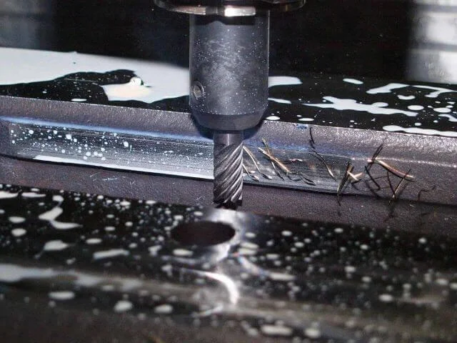
- A testing sample is CNC machined or 3D printed in a dogbone shape to create the specimen.
- The test specimen is inspected to ensure no notching or cracks are present due to the manufacturing process. There should also be no surface defects that may adversely affect the test.
- If testing 3D printed materials, a second inspection of the test specimens is carried out to examine the direction of the layering of the material to confirm the print orientation of the part.
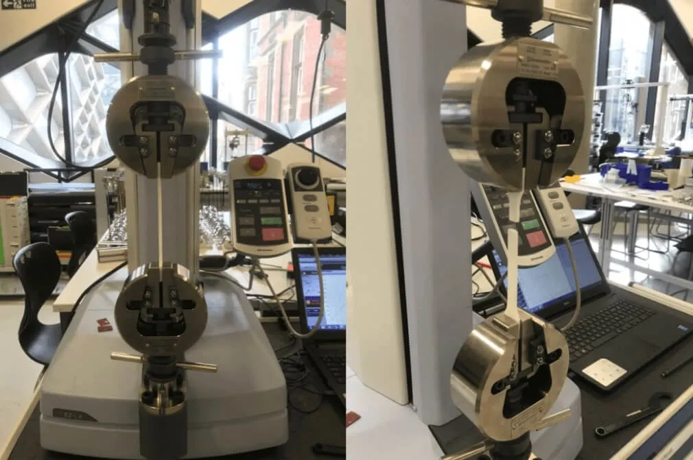
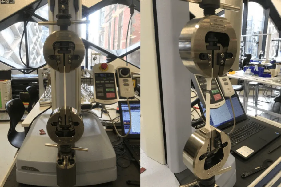
- The deflection speed should be set and prepared to record load elongation data on the tensile testing machine.
- The specimen is then loaded into the machine, force zeroed, and the tensile test starts.
- Data will record electronically into text files. A live load-elongation curve will be displayed on the computer screen to give a visual representation of how the material responded.
- When the specimen fractures, the part is removed, and the test is complete.
- The data collected is used to create a stress-strain curve.
What are the mechanical properties on a stress-strain curve?
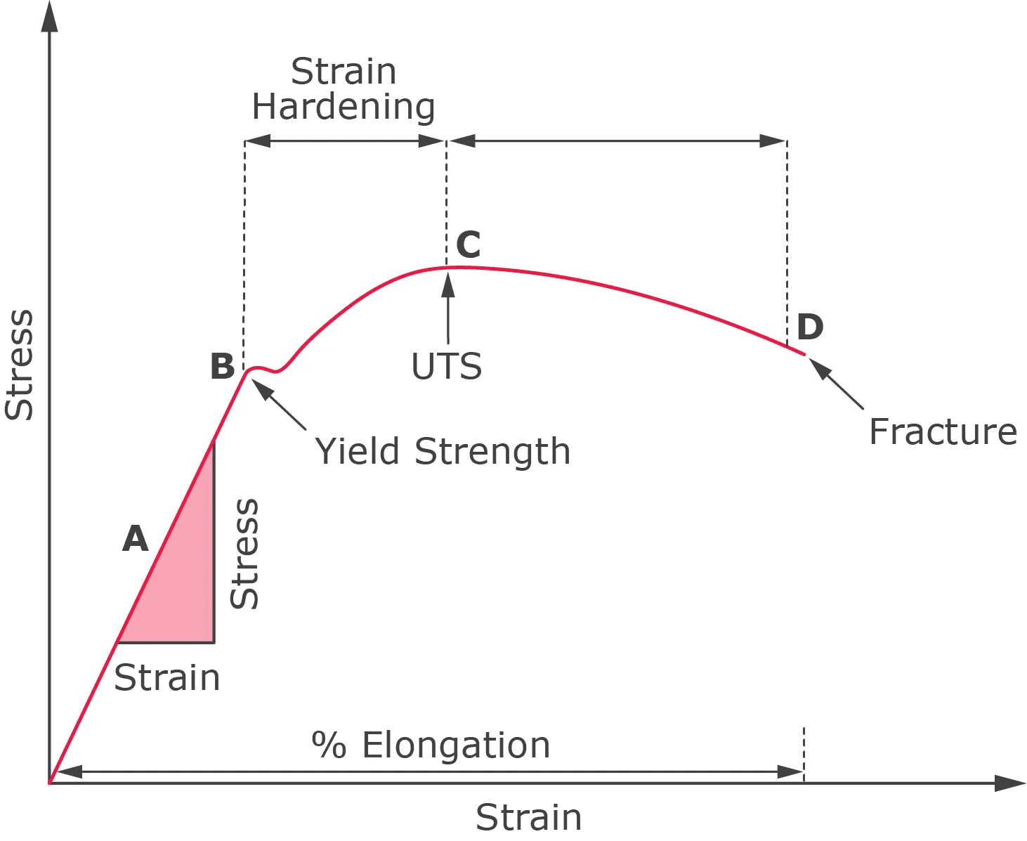
Hooke's Law (Point A)
Generally, most materials will exhibit a linear relationship between the applied force and elongation of the specimen for the initial section of the test. This linear region is governed by Hooke's Law, which states the ratio of stress to strain is constant. This constant is known as the 'Elastic Modulus' or 'Young's Modulus'. Young's modulus is a measure of the stiffness of the material and only applies in the initial linear region of the curve. The specimen will return to its original unstressed geometry within this elastic region when the tensile load is removed.
Yield Strength (Point B)
The point at which the material no longer obeys Hooke's law is the 'Elastic limit'. This point is indicative of the materials' Yield Strength' and is defined as the stress applied to the material at which plastic deformation starts to occur. Beyond this point, permanent deformation takes place, and the material reacts plastically to any additional load. It will not revert to its original unstressed geometry once the load is removed.
Ultimate Tensile Strength (Point C)
One of the essential properties determined in material testing is the ultimate tensile strength (UTS). This is the maximum stress that the material can withstand during the test. Depending on the characteristics of the material (brittle/ductile), the UTS may or may not equate to the material's strength at break. However, this can also vary depending on the ambient temperature.
Point of Failure (Point D)
This is the point at which the material cannot withstand any further stress being applied and ruptures. The stress associated with this point is known as the breaking strength.
What is a hardness test?
Hardness testing is used to determine a material's resistance to indentation and gives an insight into the material's mechanical properties. It can be used to gauge a material's strength, wear resistance and toughness. It is a non-destructive testing method where a constant load is applied to create an indentation in the material. The indentation is then measured to calculate the material's hardness. The two most commonly used testing methods are the; Rockwell testing method and the Vickers testing method.
What is a Rockwell test?
The Rockwell hardness test is the most commonly used hardness test around the world. It is a quick and easy testing procedure that can be carried out on almost all materials. It is non-destructive and only leaves a slight indentation on the material. The test measures the permanent depth of indentation produced by an indenter at a set force. Softer materials use the HRB scale, and harder materials use the HRC scale.
What is the Rockwell testing procedure?
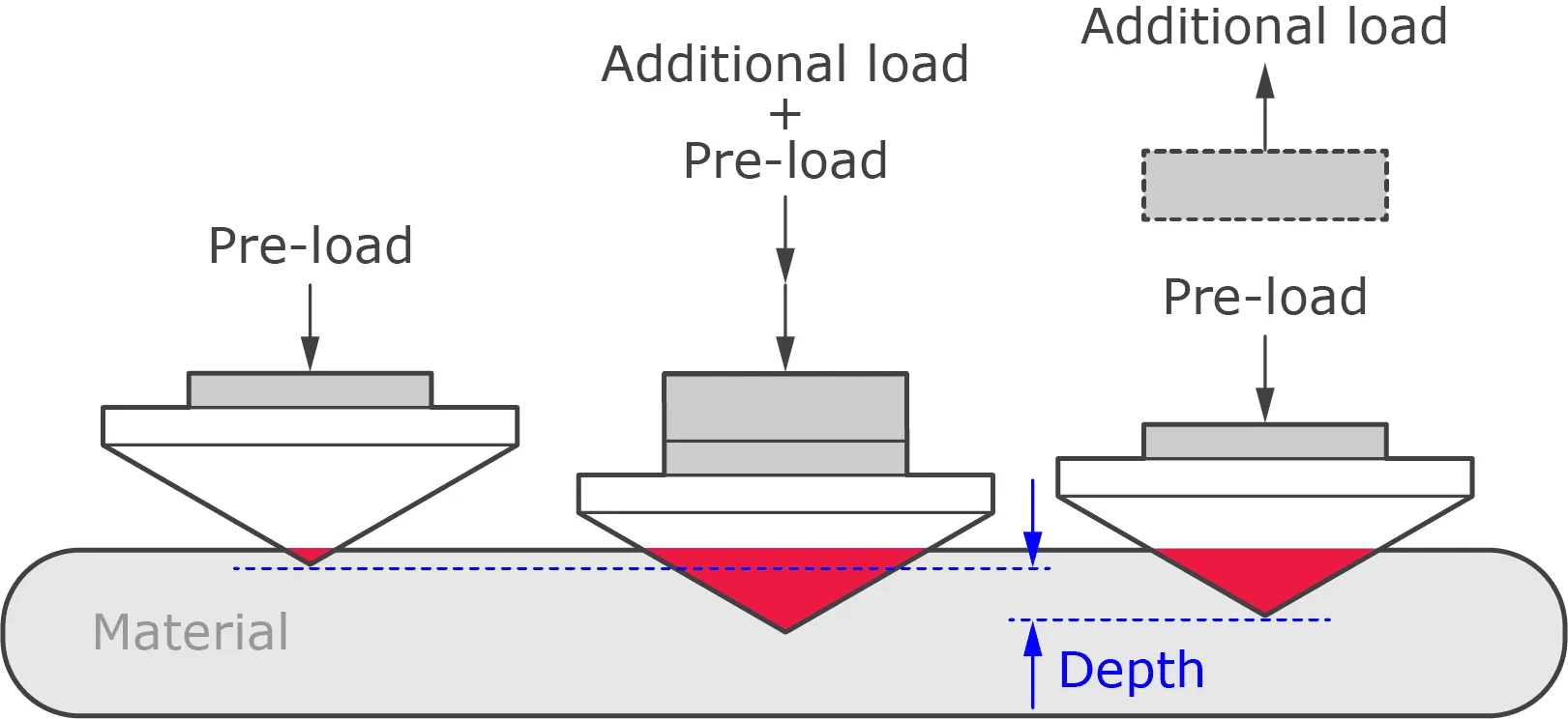
- A small preliminary force is applied to the test specimen using either a diamond cone or steel ball, known as a preload. This preload breaks through the material's surface to reduce any surface finish effects.
- The preload force is held, and the indentation depth is measured to give a baseline depth.
- An additional load, called the major load, is applied to the material to reach the testing load.
- The major load is held for a set amount of time to allow for elastic recovery and then reduced to the preload force.
- The final indentation depth is measured, and the Rockwell hardness is calculated from the baseline and final depth measurements.
What is an impact test?
An impact test, also known as a V-notch test is used to calculate the amount of energy absorbed by a material during impact. It is used to calculate the toughness of a material, the greater the resistance to impact, the tougher the material is considered to be. The testing method is defined as the kinetic energy required to fully fracture the test material in one impact. Two test methods used are; a swinging pendulum and the more commonly used Charpy impact test.
What is a Charpy impact test?
The Charpy impact test measures the kinetic energy required to break either a U-notched or V-notched specimen in a single impact. The testing method is simple and cheap to conduct, however, it is a destructive testing method. The specimen is placed horizontally on two unclamped supports. Tests can be performed at various temperatures to see how a material behaves in different conditions and work out a material's minimum service temperature.
What is the Charpy impact testing procedure?
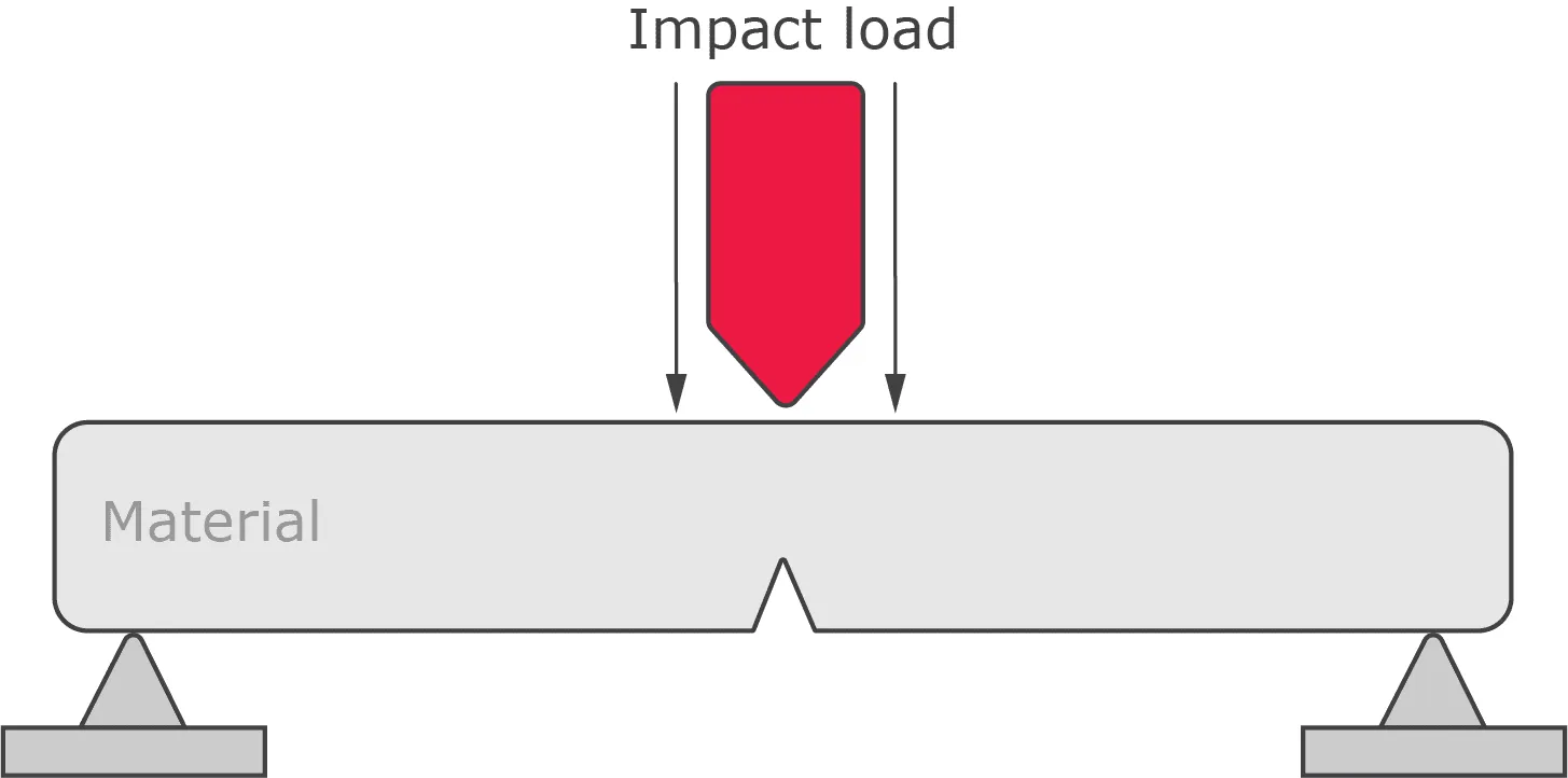
- A test piece is manufactured with a V-notch: 2mm deep, with a 45° angle and 0.25mm radius along the base.
- The test piece is placed onto supports at either end so it is stable but is not clamped down.
- An impact load is used to strike the opposite side of the notch. If the test piece does not break a heavier impactor is used until the test piece fractures.
- The energy absorbed by the test piece is calculated by measuring the decrease in motion of the impactor. The impact performance is calculated by dividing the total energy for fracture by the fracture area.
Additional testing methods
It can also be important to understand the exact chemical composition of a material to ensure the material you are working with meets the required specification. The best way to check the chemical composition of a material is to perform an Optical Emission Spectrometry test.
What material testing does Get It Made offer?
Here at Get It Made, we can provide independent 3rd party material identification and testing for projects using certified labs such as SGS and Rotechlabs. Contact a member of our team today for advice and information on what would work best for your project.
Leave it to our manufacturing specialists
Get a 24 hour, engineer made quote and design review to start your manufacturing project off on the right foot

Get your production-ready quote in 24 hours
All projects are reviewed by real engineers to ensure accuracy, catch mistakes and unlock DFM improvements


Our services
From 3D printing to CNC machining, we’re experts in manufacturing bespoke precision parts on tight time-frames

Other services
It’s rare you only need CNC machining services. We offer 3D printing, moulding, casting, extrusion, fabrication, assembly, welding & more.
Get your production-ready quote in 24 hours
All projects are reviewed by real engineers to ensure accuracy, catch mistakes and unlock DFM improvements
Working with Get It Made for all our prototyping was an absolute pleasure. Next to immediate response, fast lead times, often arriving before the stated date. Their attention to detail and customer service were second to none. and all at the most competitive price point that could't be beaten in the U.K.


Get It Made are at top of their game when it comes to reliability and quality. We trust Get It Made to deliver parts on time and within tolerance. We can't speak highly enough of their customer service. Get It made are quick to reply to enquiries and keep you well informed throughout the whole process.

Get It Made were able to deliver an accurate and quick service delivering a set of high fidelity prototypes expertly finished, ready for user testing. They offered a range of fabrication options and materials to choose from, tailoring the service to our specific budget, timeframe and material requirements. Can't recommend enough.

Get It Made have over the years been able to take on from simplest to the most complicated of jobs with ease, providing expert advice, good prices and reliable lead times. No job has been too big or too small, either in size or volume. We would strongly recommend Get It Made; you won't be disappointed!

We initially started working with Get It Made, as we needed a high quality product developed within a very short lead time. The entire process went very smoothly and we received the products ahead of schedule. We were pleased with the final results and we found working with Luke very easy, as he offered good technical advice.

When we were looking to have parts manufactured, we had tight deadlines with an even tighter budget. Get It Made understood our constraints and worked with us closely to get our parts to a higher standard than we expected. I can not recommend Get It Made enough. They are professional, communicative, and the parts are fantastic.

The Get It Made team are very responsive and knowledgeable, fully owning a project throughout, providing superb communication. Transparent pricing structure and rapid quotation turnaround is by far the quickest I've experienced, reducing time to manufacture. Get It Made are a pleasure to work with.

Bespoke quote in 24 hours
Get It Made is proud to provide a human service. Get a quote and free design review by an experienced engineer to see how we make manufacturing simple.