Understanding the CNC Milling Process: A Beginner’s Guide
This article will cover the basics of the CNC milling process. If you would like a learn how to design parts for CNC milling check out our guide here.
What is CNC Milling?
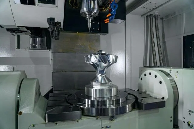
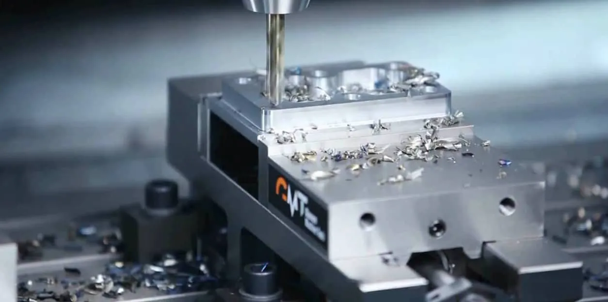
Like other subtractive manufacturing forms, CNC (Computer Numerical Control) milling works by removing material to create a final design. The CNC Milling process involves multi-point cutting tools controlled by a computerised programme that reads and translates machine paths. These machine paths originate from CAD/CAM software (Computer-Aided Design/Manufacture) programmes used to create a computerised design of the product.
In this article, we're going to delve a little deeper into the setup and functioning of CNC mills, taking a look behind the scenes at their various functions and uses.
CNC Milling Machine Function
The CNC machining process works by the machine reading its instructions from a design inputted on a CAD programme. These part designs can be 2D or 3D. Once completed, the designs are converted into a machine-readable format. CAM (Computer-Aided Manufacturing) software then exports this to a CNC machine programme, which acts as the instructions to direct each move that the machine will have to make to replicate the CAD design with the chosen material.
{{cta-banner}}
CNC Milling Machine Setup
Before the milling manufacturing process can commence, the machine needs to be set up with the right CNC machine tools for the job. The operator will also place the workpiece on the work table and fix it in place with a vice or custom jigs and fixtures. These steps are essential to ensure the machine can carry out its job without the material moving out of place. When the necessary preparations are complete, the operator can launch a programme using the machine interface, and the manufacturing process can begin.
CNC Milling Manufacturing Process
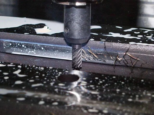
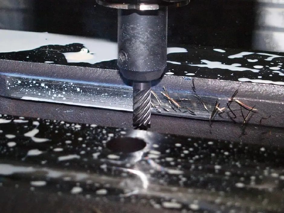
When the milling manufacturing process begins, the tools can spin at thousands of RPM and, as such, can cut into even the strongest materials with ease. During the manufacturing process, the tool and workpiece will be moved in relation to each other to access different parts of the design. The angles and direction depend on the specific design requirements of the piece, but the principle of feeding the workpiece to the rotary tool remains the same.
Types of Milling
The various types of milling can be generally categorised into the following:
- Plain milling
- Face milling
- Angular milling
- Form milling
You can read find out more about the types of CNC milling here.
As a rule, superficial surface cuts will be carried out by larger cutters, whereas a more narrow cutter can be used for finer details. Initially, more significant amounts of material will be removed with a coarse-toothed tool, then a faster, more fine-toothed cutter is used for more detailed parts of the design and for finishing.
Features of a CNC Milling Machine
A CNC Milling machine is comprised of the following features:
Worktable
This is where the material or workpiece is secured to be worked on. It’s located on top of the saddle. Depending on the type of machine being used, the worktable is adjustable horizontally, vertically, sometimes both, or not at all.
Saddle
This is just below the worktable to support it and is adjustable to fix the worktable concerning the spindle axis. The saddle, located at the top of the knee, supports the worktable. It moves parallel to the axis of the spindle. This function enables the worktable to be horizontally adjusted. This fixes the worktable in relation to the spindle axis.
Knee
Below the saddle, this supports the worktable and saddle and can be moved up and down depending on the height needed. This is an adjustable part of the machine, affixed to the column. It is adjustable along the Z-axis, depending on the specific milling operation being carried out.
Column
This is the fixed base of the machine, which can also house things like coolant or oil for the machine. The column in a CNC Milling machine is the component that provides support to other components – it’s essentially the fixed base of the machine.
Spindle
This component is driven by a motor within the column supported by it. This is what controls the machine tool.
Machine tool
The machine tool is sometimes referred to as a mill cutter. This part touches and removes material from the workpiece and will vary in type depending on the job at hand, e.g. cutter, drill, bore etc. The specifications of the machine tool vary, for example, the diameter, length, spacing of teeth, material etc. CNC Milling is so versatile largely due to the vast variety in cutting tools.
Arbour
The arbour essentially connects the machine tool to the spindle. It’s available in various lengths and diameters, again depending on the specifications of the CNC Milling machine in question.
Ram
The core function of this component is to support the spindle in vertical milling machines. It is adjustable to accommodate different positions during the milling process.
CNC Milling Machine Cutting Tools
Thread mills
Face milling tool
Face mill
Involute gear cutter
Shell mill
Cross cutter
Foam mill
Ball cutter
Fly cutter
Roughing end mill
Engraving tool
End mill
Slab mill side and face cutter
Hollow mill
Dovetail cutter
Types of milling cutter
Depending on the exact finish you are looking for, the type of cutting tool will be important. For example, some mills, such as end mills, can cut axially. Face mills, however, cannot cut axially; the cutting edges are located on the side, which has the benefit of keeping a good cutting quality and extending the lifetime of the tool. Particular types of each mill can be used for more complicated designs. For example, a rough end mill is similar to an end mill but with a more jagged edge, making the cutting process faster.
For more information about CNC Milling machines, check out Get It Made’s CNC Machining guide. If you’re looking for a quote for CNC Milling, get in touch today.
Leave it to our manufacturing specialists
Get a 24 hour, engineer made quote and design review to start your manufacturing project off on the right foot
Get your production-ready quote in 24 hours
All projects are reviewed by real engineers to ensure accuracy, catch mistakes and unlock DFM improvements
Our services
From 3D printing to CNC machining, we’re experts in manufacturing bespoke precision parts on tight time-frames
Other services
It’s rare you only need CNC machining services. We offer 3D printing, moulding, casting, extrusion, fabrication, assembly, welding & more.
Get your production-ready quote in 24 hours
All projects are reviewed by real engineers to ensure accuracy, catch mistakes and unlock DFM improvements
Bespoke quote in 24 hours
Get It Made is proud to provide a human service. Get a quote and free design review by an experienced engineer to see how we make manufacturing simple.


