
The Basics
What is MJF 3D Printing?
MJF 3D printing is an ‘additive’ process that builds a three-dimensional part layer-by-layer from a CAD file. Due to the nature of the process, the term '3D Printing' is often used interchangeably with 'Additive Manufacturing'. The process can be thought of as similar to a traditional inkjet printer; instead of printing one layer, the machine fuses powdered layers of the design's cross-section again and again until the 3D part is formed.
This manufacturing method can be considered the opposite of more conventional subtractive manufacturing methods such as CNC machining. Where you start with a block of material and ‘subtract’ the material away to form your design part.
{{cta-banner}}
How to go from an idea to an MJF part
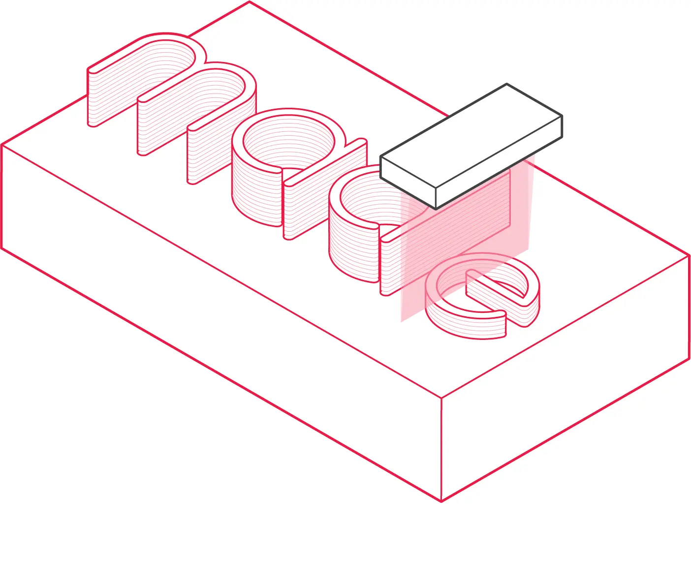
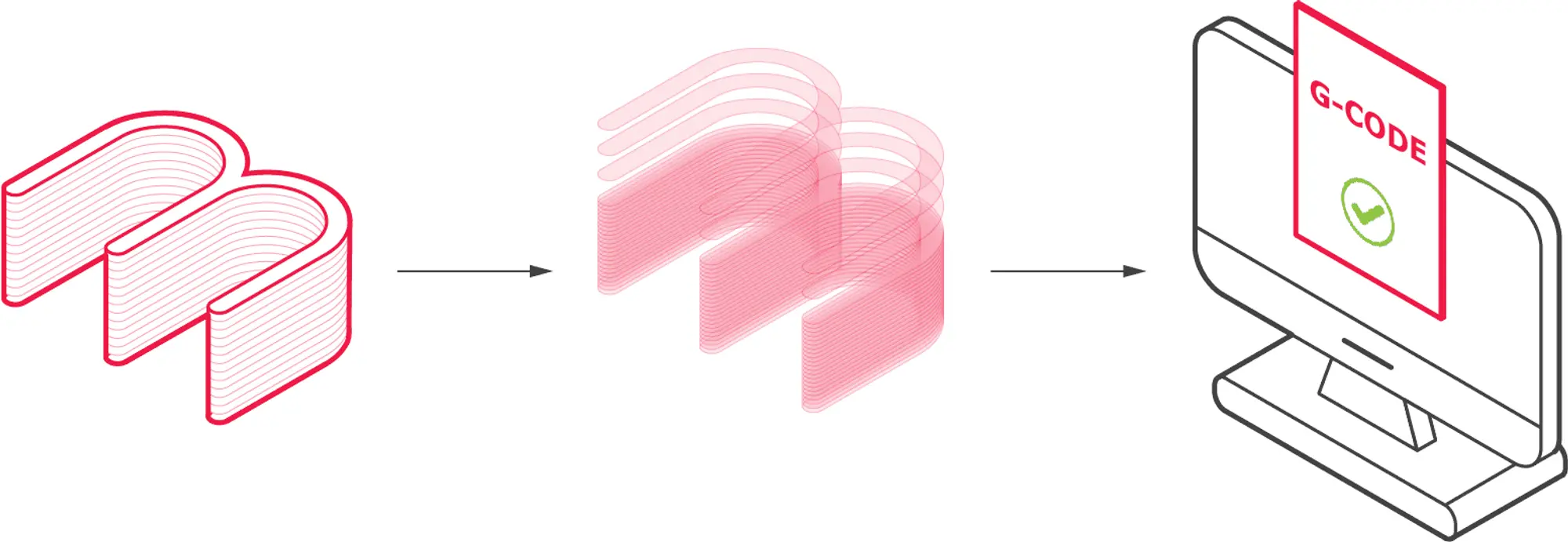
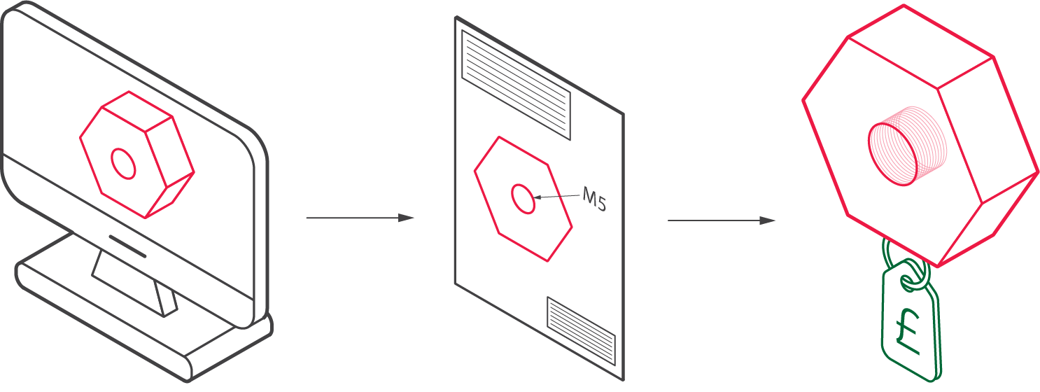
An MJF project begins with a 3D CAD file; this can be designed yourself using a CAD package or downloaded from one of many online repositories. As MJF manufactures parts layer-by-layer, the CAD file needs to be ‘sliced’ up into layers to create the printer's build path. 3D slicing software is used to configure the digital design and translate this into a code/language that can be understood by the HP machine called GCODE. The printer then has the instructions for the build path it should take, and the final 3D part is manufactured additively layer by layer.
The general process for MJF can be broken down into the following simple steps:
- A 3D CAD file is created or downloaded.
- The 3D model is sliced into 2D layers and converted into GCODE, which tells the 3D printing machine its build path.
- The part is then built up in layers through a powder medium.
- Finally, the part is left to cool before moving on to post-processing.
Depending on the size, complexity and number of parts required, MJF 3D printing can take as little as an hour. 3D printing lead times are superior to conventional processes, especially casting.
Post-processing may also be required to achieve the desired level of surface finish. Typically this can involve a light bead blast, vapour polishing or dying.
What is MJF 3D printing used for?
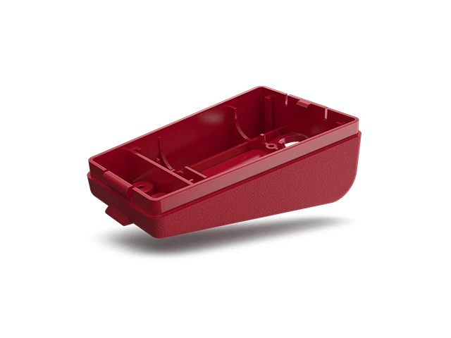
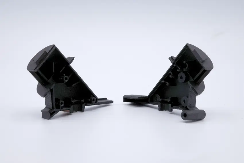
Multi Jet Fusion is an advanced 3D printing technique capable of generating functional prototypes and end-use components in as little as one day. The final parts produced by MJF have excellent mechanical properties, intricate detailing and surface finish compared to other 3D printing technologies.
.webp)
How much does MJF cost?
The exact cost of MJF varies depending on several factors. The main drivers of part cost are material cost, bounding part size, post-processing and batch size. Part complexity is less of a factor in cost compared with conventional methods such as CNC machining. This allows for complex parts to be produced with little additional cost. The best way to determine the price of a 3D printing project is to arrange a quote with a reputable 3D printing service provider such as Get It Made.
What is the Multi Jet Fusion Process?
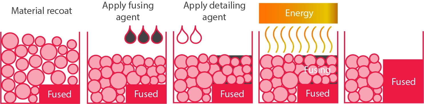
- The printer applies a layer of material powder onto the printing bed.
- An inkjet head then moves across the layer of powder, depositing both a fusing agent and a detailing agent.
- Next, an infrared heating unit scans over the print. The fusing agent causes the underlying layer to fuse or "melt" together while the detailing agent-treated areas remain in powder form.
- The powder in the areas treated with the detailing agent is shed, leading to the formation of the intended shape. The remaining powder in the lower layers also acts as a support for the layers above, reducing the need for additional support.
- HP's Multi Jet Fusion technology differs from many other 3D printing methods by applying each new material and agent layer while the previous layer is still in a molten state. This allows for a complete fusion of the layers, improving durability and detail in the final print.
- Upon completion of the printing process, the entire powder bed, along with the printed parts, is transferred to a separate processing station.
- In this processing station, most loose, unfused powder is vacuumed away, allowing for reuse and reducing waste.
- Post-processing, such as, bead blasting, vapour polishing and dying, is then performed if required.
What industries use MJF?
Healthcare and medical

MJF is very well suited to the healthcare and medical sectors due to its ability to quickly produce biocompatible custom one-off parts. In particular, custom-made orthotics and prosthetics have seen a significant rise over recent years, as MJF can create detailed lattices that can be matched to the user's body shape and skin tone.
Automotive
The automotive sector uses MJF as a sustainable option for supplying customers with spare parts. Parts can be printed on demand and with the same surface texture as injection moulded parts, meaning there is no surplus stock.

Consumer goods
.jpeg)
MJF is being utilised in consumer goods with products such as custom eyewear for children. The technology allows personal eyewear to be manufactured uniquely for each user while still being offered at an affordable price.
What are the Advantages of MJF 3D Printing?
✅ High detail
MJF produces high-resolution parts, making it ideal for components that require fine details. It can create complex geometries that are impossible with traditional manufacturing methods such as CNC machining.
✅ Fast production
Compared to other 3D printing technologies, MJF is faster as it fuses an entire layer of material at once rather than tracing a pattern. This makes it suitable for both prototyping and small to medium-sized production runs.
✅ Functional parts
MJF can produce end-use parts straight from the printer. The end products have strong mechanical properties and are isotropic, meaning they have uniform properties in all directions.
What are the Disadvantages of MJF 3D Printing?
❌ High initial cost
The cost of an MJF printer and the associated infrastructure is very high, so it is often best to work with a supplier such as Get It Made. This makes initial prototyping much more affordable for small businesses or hobbyists.
❌ Post-processing requirements
MJF parts often require additional steps after printing, such as bead blasting, vapour smoothing and dying to improve the appearance of the parts. These steps add time and cost to the overall process.
❌ Limited materials
A key drawback of MJF is its narrow range of supported materials, primarily restricted to variations of Nylon, TPU and stainless steel.
3D Printing Design Guidelines
This section outlines some of the key design considerations that will help improve the manufacturability of your MJF parts, resulting in higher-quality prints:
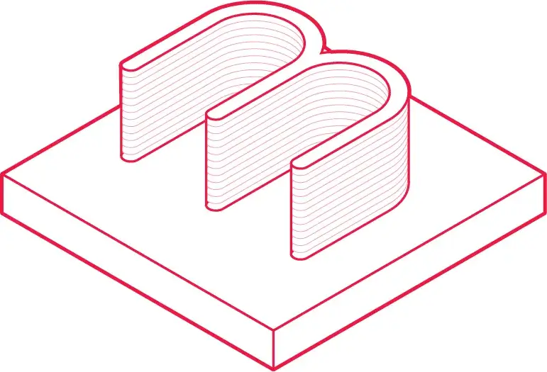
Wall Thickness
The wall thickness is the distance between one surface of a 3D model to its opposite surface. An unsupported wall is connected to the rest of the part by only one surface. It has a minimum thickness it can be printed without warping.

Vertical wall thickness: 0.3 mm
Horizontal wall thickness: 0.5 mm
Pin Diameter
A pin is a tall thin feature with a circular cross-sectional area. There is a minimum diameter a pin can be printed without a build failure or warping.
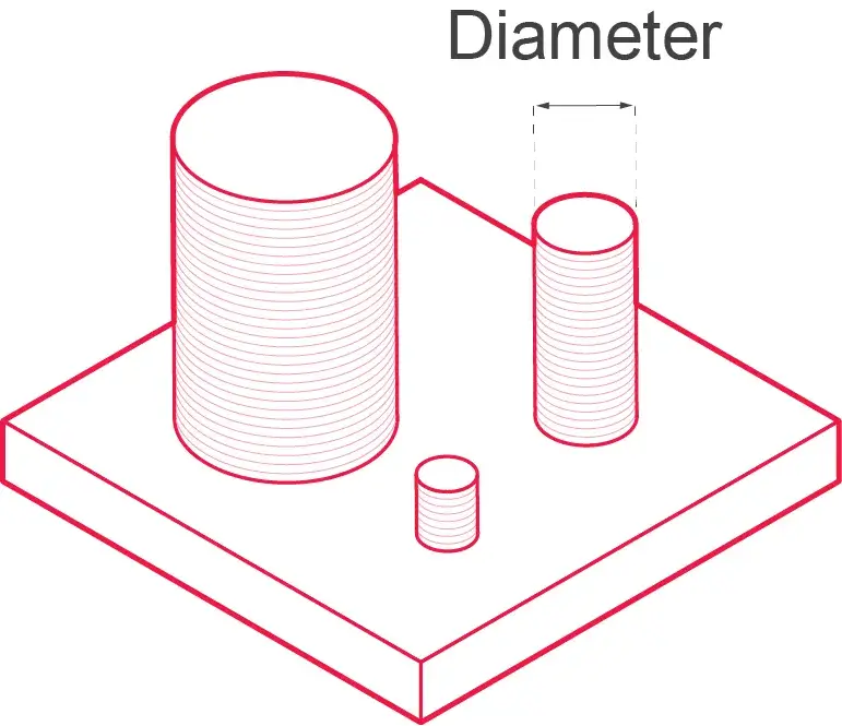
Diameter at a height of 10 mm: ø0.5 mm
Engraved Detail
An engraved detail is a recessed feature below the surface of a part. Recesses have a minimum depth; otherwise, they will not be visible due to a process's layer height.

Font size: 6 pt (2.1 mm) or larger
Depth: 1.0 mm or deeper
Embossed Detail
An embossed detail is a shallow feature that protrudes from the surface of a part. Embossed detail has a minimum height. Otherwise, they will not be visible due to a process's layer height.
Font size: 6 pt (2.1 mm) or larger
Depth: 1.0 mm or deeper
Moving Parts
Moving parts are two or more individual parts printed on the same print bed. A minimum clearance distance is required for the parts to move freely and not fuse.

The separation between parts: 0.7 mm or larger
Hole Diameter
Holes have a minimum diameter that can be printed without the risk of the hole closing during manufacturing.
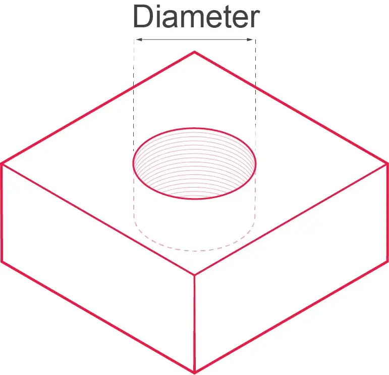
Min hole diameter at a 1 mm depth: ø0.5 mm
Aspect ratio
Long and thin parts are prone to uneven cooling, potentially causing uneven shrinkage along the part. This can result in a distorted shape that deviates from the intended design.

Maximum aspect ratio of 10:1
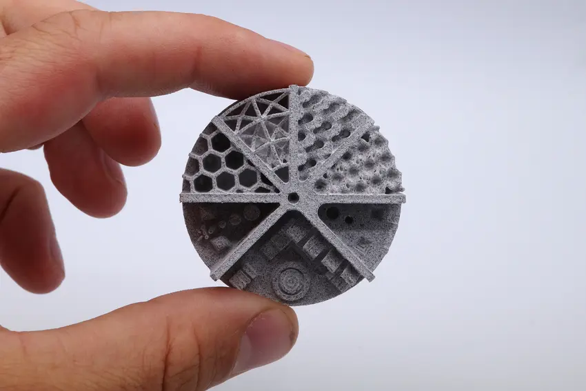
Lattice structures
Lattice structures need to have a minimum spacing between struts to allow material to fit inside the part easily.

Lattice minimum gap: 0.5 mm
3D Printing Materials
When selecting a material, it is essential to consider the mechanical properties, surface finishing and cost. Get It Made offers Nylon 12 (PA 12) as it offers a great combination of performance and aesthetics, making it an ideal choice for fabricating end-use components. The table below displays the key material properties:
If you require a specific material other than PA12, please get in touch with us, and we will do our best to source the material for you.
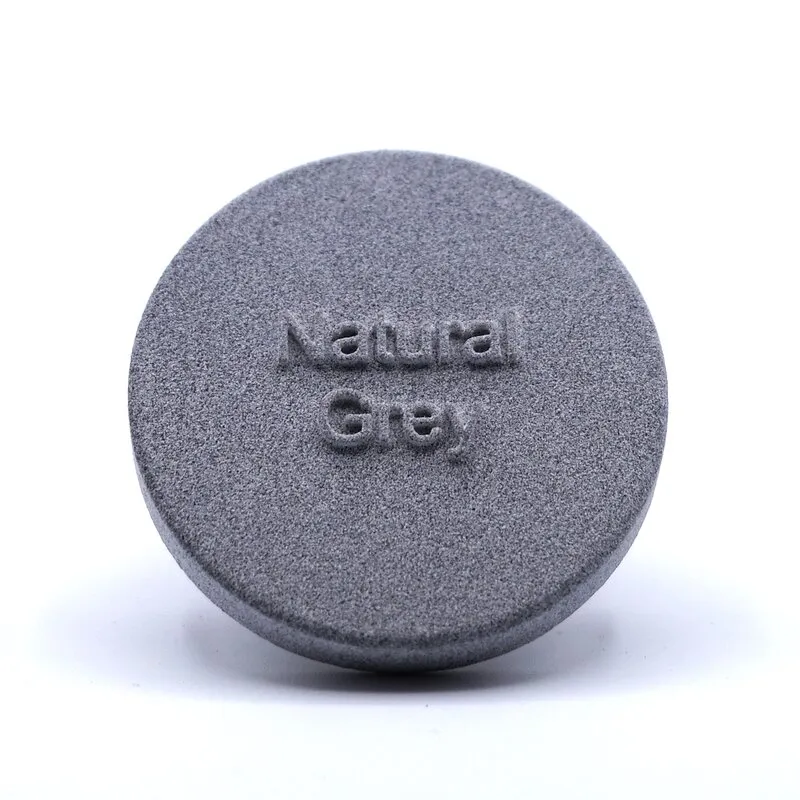
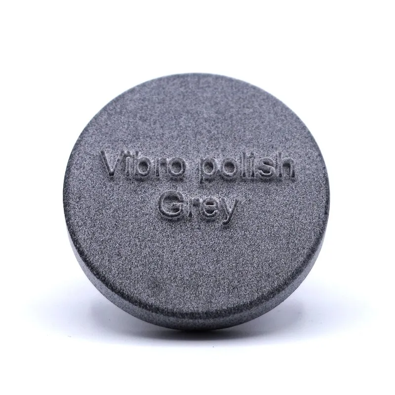
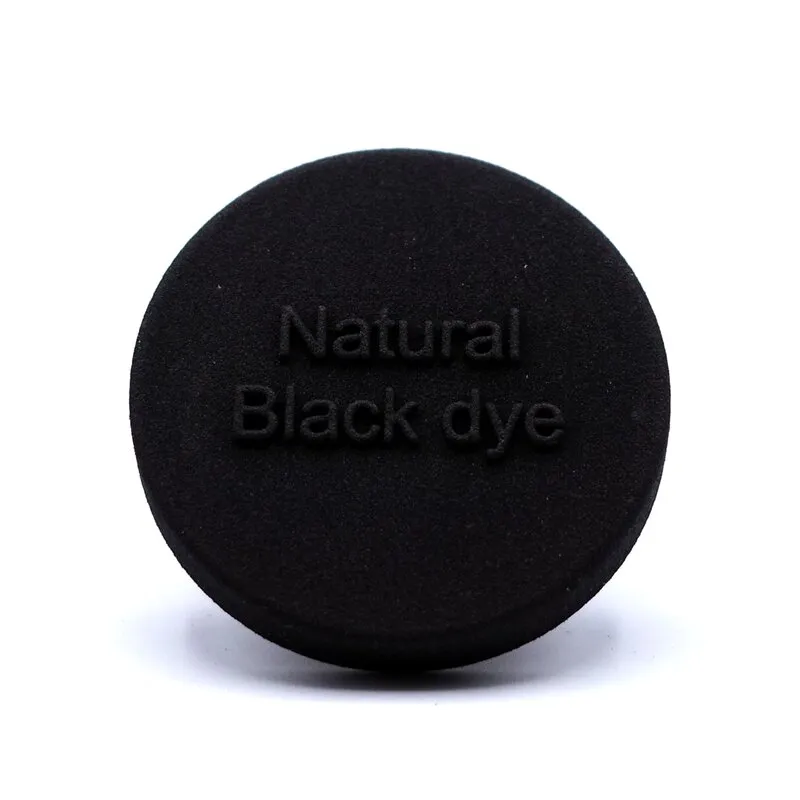
MJF finishing methods
.webp)
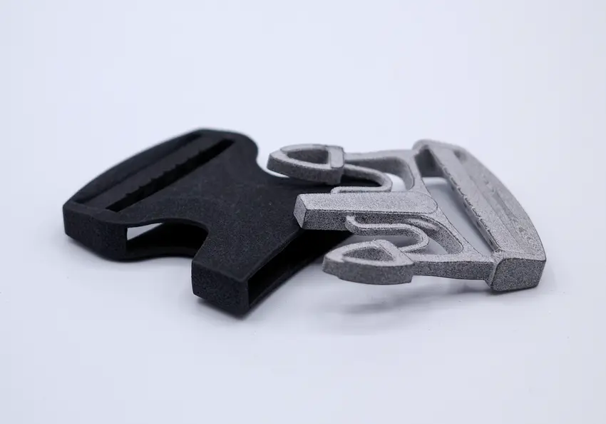
Left to right: Natural Grey, Natural Black, Vibro Polish Grey, Vibro Polish Black, Shot Peen Black.
As printed
The As Printed finish is the baseline standard of our MJF 3D printing service, facilitating a variety of desirable attributes. Post-printing, the MJF parts undergo a light blasting process to remove the residual powder. This gentle ablation generates a uniform finish with well-defined edges and almost indiscernible layer lines. This approach leaves MJF parts with a matte, grainy texture, offering an inherent rough charm.
✅ Cost-effective
✅ Precise, sharp edges
❌ Surface roughness
❌ Can have some residual powder
Vibro polishing
Vibro Polishing is a finishing technique that enhances the surface of MJF parts by smoothing out the outermost layer. The MJF parts are placed inside a vibratory tumbler (vibro-polisher) which is filled with the polishing media. The media consists of smooth ceramic chips that gently rub away on the part's surface, which gradually smooths and polishes it. The end result is an MJF part with a more uniform and aesthetically pleasing surface finish.
✅ Smooth service finish
✅ Ready for painting
❌ It can damage very thin/sharp features
❌ Reduces the size of parts
Shot peening
Shot peening is a process where small spherical beads are shot at the surface of MJF parts, creating tiny indentations. These indentations create beneficial compressive residual stresses beneath the surface, making the parts more resistance to fatigue and stress-corrosion cracking. Shot peening is a process that enhances not only the mechanical properties, but also the aesthetics of the surface. At Get It Made, we use the shot peening machine by DyeMansion, specifically designed for post-processing MJF parts.

✅ Increased fatigue resistance
✅ Improved stress corrosion cracking
❌ Some small cavities can’t be processed
❌ Increases part cost
Black dye
At Get It Made, we use the DyeMansion DM60 machine, which uses their patented DeepDye Colouring (DDC) process. Parts are submerged in a bath of dye solution, where they are exposed to a combination of heat and pressure that allows the dye to penetrate into MJF parts. This dyeing technology penetrates the colour deep into the parts, giving them a superior aesthetic finish and making them scratch resistant.
✅ Improved aesthetics
✅ End-use finish
❌ Additional cost
❌ Longer production time
Combing finishing methods
Get It Made integrates Vibro Polishing and Black Dye for MJF parts, creating a striking finish. After Vibro Polishing smoothens the parts, they are submerged in a black dye bath using the DyeMansion DM60 machine and its DeepDye Colouring process. This two-step procedure creates a sleek, uniform, and scratch-resistant surface while the black dye deeply penetrates the parts, offering a superior aesthetic appeal.
Cost Reduction Tips For 3D Printing
This section will outline some simple adjustments that can be made to help reduce the overall cost of your part. Two main areas will significantly affect the cost of your part:
- Design - Solid designs with a lot of material are expensive.
- Quantity - Cost per unit reduces with increased quantity due to fixed setup costs.
Design
Nesting
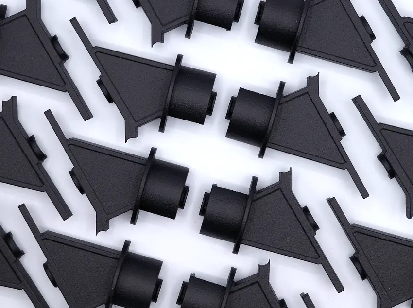
Nesting MJF parts involves strategically placing parts in the print bed to optimise space usage, reduce print time, and hence lower part cost. The cost of a printing job depends on the total volume of material used, and the aim of nesting is to minimise this overall usage. MJF printers can produce parts with complex geometries without the need for support structures, allowing them to be nested in three dimensions. Parts can be placed within the unused spaces of other parts or even stacked vertically, provided they don't interfere with one another's structures. This utilisation maximises the number of parts printed in a single batch, leading to more efficient use of resources and reducing the cost per part.
Hollow Out Your Part
A significant proportion of the costs involved in 3D printing is related to the amount of material used. An effective way to reduce the amount of material used is to hollow out the centre of your design to create an outer shell. Pay careful attention to the wall thickness; if you go too thin, the part will lose its structural integrity. Be sure to include escape holes for the powder to escape; otherwise it’ll remain stuck inside your part!
Incorporate a Lattice
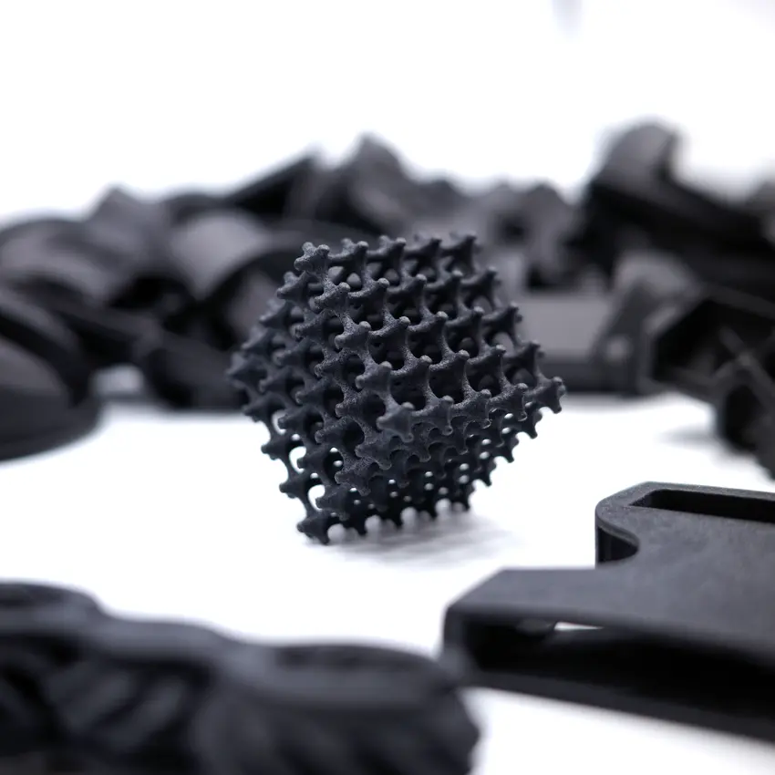
Another option is to replace solid features in your design with an internal lattice. Lattices are great as they can reduce the amount of material used without compromising the structural strength of your part substantially. Most CAD software will allow you to incorporate a basic lattice into your design, known as percentage infill. Again, you will need to include escape holes for the powder.
Reduce Part Siz
The part size directly correlates to the cost as a bigger part requires more material and an increased print time. If manufacturing a design for proof of concept, consider scaling down the model size to reduce cost and lead time. This will allow you to get through the prototyping phase faster and cheaper than a full-scale design.
Optimise Your Design
The main drivers of cost for 3D printing are the amount of material used and the manufacturing time. Therefore, unlike a traditional manufacturing process such as CNC machining, adding extra holes to your part can reduce the part cost instead of increasing it! This is because less material is used with a reduced production time.
Quantity
Unit cost can be reduced slightly by increasing the order volume of your part. Our manufacturing team needs to programme the machine, set up the part, and perform a varying degree of post-production finishing, which is a fixed cost. The fixed price can be shared across all the parts by manufacturing multiple parts simultaneously, making each more economical.
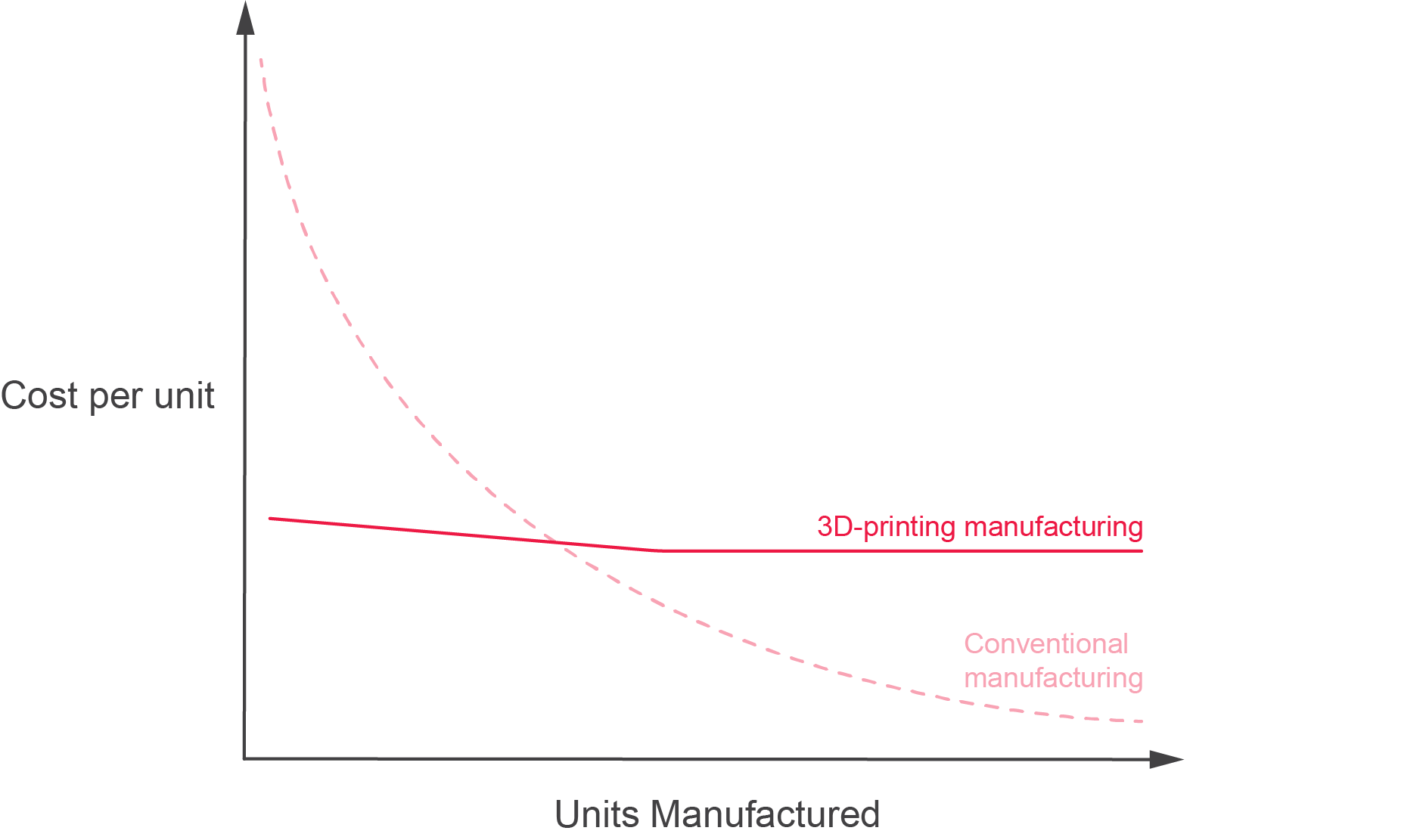
3D printing is an excellent option for low-medium volume production; however, moving into high-volume production, CNC machining and injection moulding becomes a more cost-effective means of production. See the graph for a visual representation of economies of scale.
Getting Your Part Made
1) Design and Export your CAD File
Use the 3D Printing Design Guidelines to help design your parts for machining. Then please export your 3D CAD files to STEP, IGS or PARASOLID format. We can accept STL files for 3D printing projects. We cannot accept OBJ files as they do not correct geometric data for manufacturing.
2) Create an Engineering Drawing
We highly recommend sending supporting PDF Engineering Drawings for each part. This is required when a part has: thread holes, critical dimensions, tolerances, and specific finishing requirements. In some circumstances, we can accept an annotated screenshot, such as highlighting a threaded hole.
3) Get a Quote in 24 hours
Please request a free quote today, and one of our engineers will personally review your project within 24 hours. They will then help fine-tune your project to ensure you get the best possible price and lead time for your 3D Printed parts!
3D printing technology continually evolves, and machine and material prices have become more economical. When considering 3D printing for your next project, take the time to speak with experts such as Get It Made to discuss the proper 3D printing process for you.
You can explore Get It Made’s 3D printing services on our website or head to our blog for more information and insight about our range of services.

Obsessed with making sure we offer the best service possible in the manufacturing industry. Father to one, and hopefully many more!


Need custom metal and plastic parts?
Get 10% off your first order
No newsletter, no marketing, just a discount code for custom parts.